
Method and device for Fourier domain iterative splicing super-resolution microscopy based on surface wave illumination

A super-resolution and surface wave technology, applied in measurement devices, material analysis, material analysis by optical means, etc., can solve problems such as complex manipulation, and achieve the effect of fast imaging speed and simple structure

Inactive Publication Date: 2017-01-04
ZHEJIANG UNIV
View PDF5 Cites 13 Cited by
  • Summary
  • Abstract
  • Description
  • Claims
  • Application Information

AI Technical Summary

Problems solved by technology

The method of obtaining surface waves propagating in a certain direction through a prism is simple and easy, but when it is necessary to change the direction of surface wave propagation, the manipulation will become complicated

Method used


Image

  • Method and device for Fourier domain iterative splicing super-resolution microscopy based on surface wave illumination
  • Method and device for Fourier domain iterative splicing super-resolution microscopy based on surface wave illumination
  • Method and device for Fourier domain iterative splicing super-resolution microscopy based on surface wave illumination

Examples


Embodiment 1

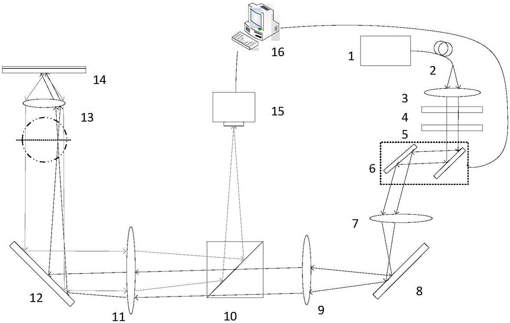
[0063] Such as figure 1 As shown, a Fourier domain iterative splicing super-resolution microscopic imaging device based on surface wave illumination propagating in different directions generated by a two-dimensional scanning galvanometer, including a laser 1, an optical fiber 2, a first lens 3, and a polarizer 4 , a half-wave plate 5, a two-dimensional scanning mirror 6, a scanning lens 7, a first mirror 8, a second lens 9, a dichroic prism 10, a field lens 11, a second mirror 12, an objective lens 13, and a sample 14 , CCD 15, computer 16.

[0064] use figure 1 The frequency-shifting super-resolution microscopy method realized by the shown device, its process is as follows:

[0065] (1) The laser 1 emits an illumination beam, which is collimated by the fiber coupling 2 and the first lens 3 to obtain a collimated beam; the collimated beam is modulated into a parallel linearly polarized light by a polarizer 4, and the parallel linearly polarized light is 1 / 2 After the wave...

Embodiment 2

[0076] Such as Figure 7 As shown, a Fourier domain iterative splicing super-resolution microscopic imaging device based on surface wave illumination that propagates in different directions through a digital micromirror (DMD), including a laser 1, an optical fiber 2, a first lens 3, and a polarizer 4. Half-wave plate 5, scan lens 6, second lens 7, digital micromirror (DMD) 17, third lens 9, beam splitter prism 10, field lens 11, second mirror 12, objective lens 13, sample 14, CCD 15, computer 16.

[0077] use Figure 7 The frequency-shifting super-resolution microscopy method realized by the shown device, its process is as follows:

[0078] (1) The laser 1 emits an illumination beam, which is collimated by the fiber coupling 2 and the first lens 3 to obtain a collimated beam; the collimated beam is modulated into a parallel linearly polarized light by a polarizer 4, and the parallel linearly polarized light is 1 / 2 After the wave plate 5 is the parallel linearly polarized li...


PUM


Abstract

The invention discloses a method for Fourier domain iterative splicing super-resolution microscopy based on surface wave illumination. The method comprises the following steps of (1) by changing the illumination angle of incident illumination light, stimulating the surface wave which is propagated along different directions at an interface of a sample and air; (2) enabling a surface wave illumination sample to generate frequency spectrum shifting along the corresponding transverse wave vector, and shifting a high-efficiency component of an object to the lens low objective low passband range; (3) enabling a CCD (charge coupled device) to shoot up an image corresponding to each illumination angle, substituting into a Fourier domain iterative splicing (FP (Fabry-Perot)) algorithm, and finally reconstructing the strength and phase distribution of the complicated sample. The invention also discloses a device for the Fourier domain iterative splicing super-resolution microscopy based on the surface wave illumination. The method has the advantages that the restored quantitative phase does not need to be obtained by interference; when the etching depth of the restored etching grid sample is calculated, the accuracy is verified through AFM (atomic force microscope) detection; the broad application prospect is realized in the material and life sciences.

Description

technical field [0001] The invention belongs to the field of microscopic observation and measurement, and in particular relates to a Fourier domain iterative mosaic super-resolution microscopy method and device based on surface wave illumination. Background technique [0002] The challenge of obtaining high-resolution information about samples has driven the remarkable development of many super-resolution microscopy techniques in recent decades. According to different illumination methods, these microscopic imaging techniques can be roughly divided into two types: the first one is to directly expand the optical transfer function (OTF) of the imaging system by reducing the optical transfer function (PSF) of the imaging system, for example: scanning common Focusing microscopy, stimulated emission depletion microscopy (STED), ground state depletion microscopy (GSD) and fluorescence differential microscopy are typical representatives. Another way is to use wide-field imaging, w...

Claims


Application Information

Patent Timeline
IPC IPC(8): G06T3/40G01N21/01
CPCG01N21/01G06T3/4038G06T3/4053
Inventor 刘旭刘秋兰匡翠方方月
Owner ZHEJIANG UNIV
Learn More