Wet mill for industrial processing of concrete admixtures

A technology of admixture and wet mill, which is applied in the direction of grain processing, etc., can solve the problems of long feeding time, long time, and failure to reach industrialized production, so as to achieve large processing capacity, improve economic benefits, and reduce waste of resources Effect

Active Publication Date: 2019-02-26
湖北青垚环境有限公司
View PDF6 Cites 0 Cited by
  • Summary
  • Abstract
  • Description
  • Claims
  • Application Information

AI Technical Summary

Problems solved by technology

Applying wet mills in other fields to the production of slurry admixtures for concrete will inevitably lead to unacceptable phenomena, which are mainly manifested in: 1. Low output. The production of concrete in commercial mixing stations is calculated in tons or cubic meters, while The daily processing capacity of the existing equipment obviously cannot keep up; 2. The equipment is extremely easy to damage, because the gel material is processed, the characteristics of the gel material determine that it is easy to harden, and it is easy to be blocked during use; 3. Efficiency Low, the traditional feeding method of wet mill adopts pumping pre-mixed slurry or feeder feeding, and the feeding port is small, resulting in too long feeding time, which is far from meeting the requirements of industrial production; 4 1. Wet mills in various fields have their own defects, and the problems become more prominent after being applied to the production of slurry admixtures. For example, some wet mills have no heat dissipation and cooling system, and the cementitious materials may hydrate during the wet grinding process. The heat release exacerbates the seriousness of the problem; 5. High energy consumption. The general wet mill adopts the method of feeding from the bottom to discharging from the top. The slurry stays in the cylinder for too long. Large dose of dispersant; 6. It is extremely inconvenient to clean. Due to the structure of bottom feed and top discharge, a large part of the slurry is mixed in the grinding balls, and cleaning requires a lot of water resources and a long time

Method used


Image

  • Wet mill for industrial processing of concrete admixtures
  • Wet mill for industrial processing of concrete admixtures
  • Wet mill for industrial processing of concrete admixtures

Examples


Embodiment Construction

[0012] The present invention will be described in detail below with reference to the accompanying drawings.

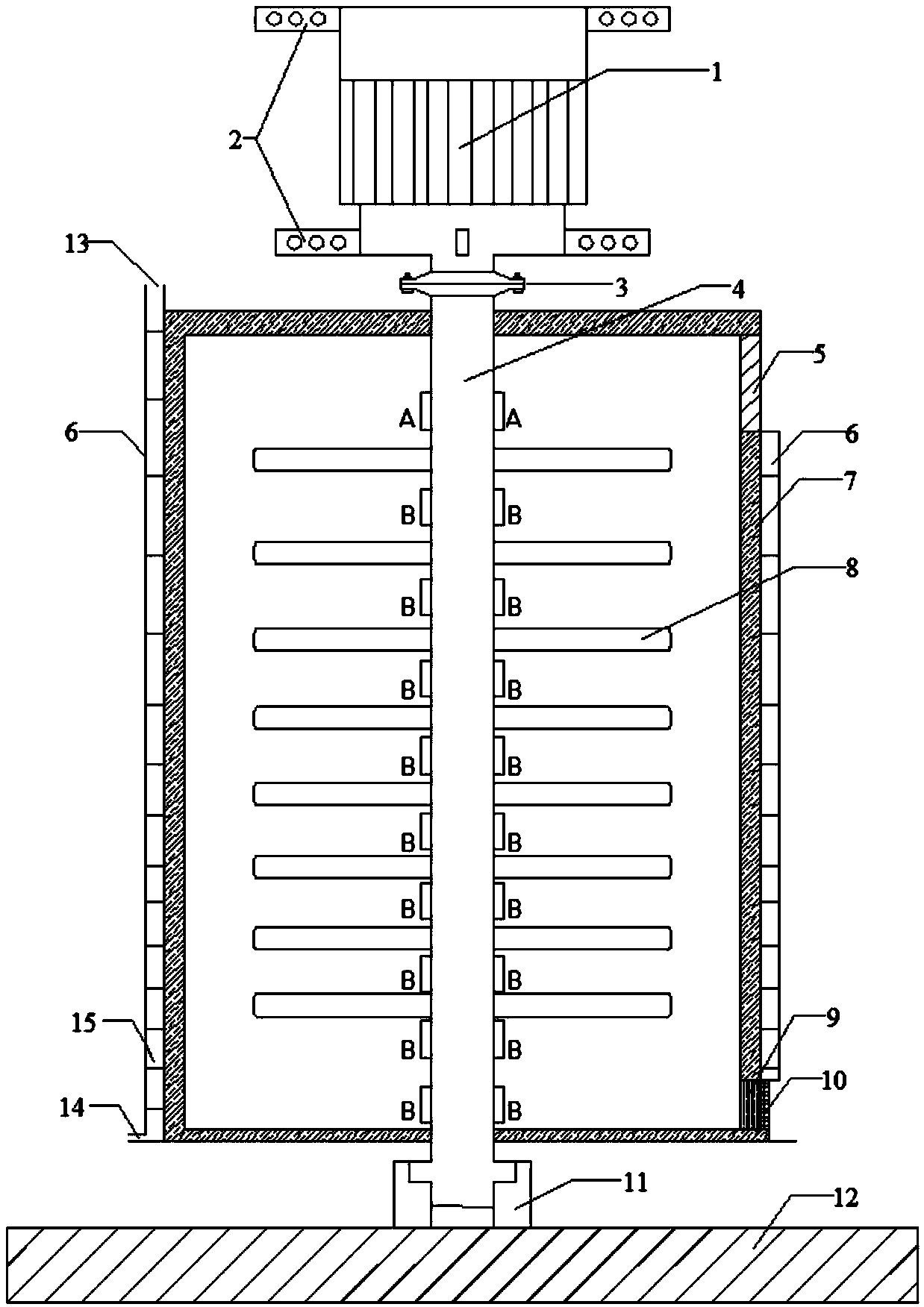
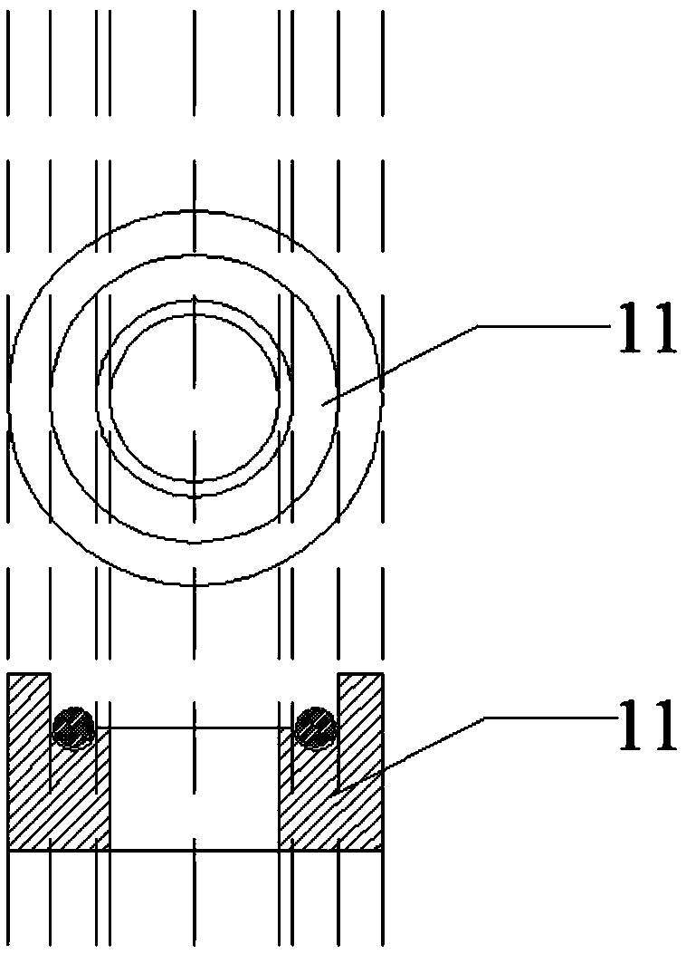
[0013] refer to figure 1 , 5 , in order to prevent polarization and ensure the stability of the body, the cylinder 7 is connected to the embedded component 17 through the connecting member 18, and the embedded component 17 is fixed on the reinforced concrete column 16. The upper part of the rotating shaft 4 is connected with the power equipment 1 through the coupling 3 , and the lower part is carried by the bearing member 11 . The bearing member 11 is firmly connected with the basic concrete structure 12, that is, it is carried on the basic concrete structure. The rotating shaft 4 runs through the cylindrical body, and the penetrating part is sealed by a sealing ring. The power equipment 1 is fixed on the bracket 16 through the connecting member 2 .

[0014] The cylinder is 3-5.5m high and 1.5-2.5m in diameter. Due to the large cylinder, the bracket 16 adopts the c...


PUM


Abstract

The invention relates to a wet grinding machine for industrial treatment of concrete admixtures. An embedded component is connected onto a tube body; the embedded component is fixed on a reinforced concrete column; power equipment is connected onto a rotating shaft, and the lower part is born by a bearing component; the bearing component is provided with a wear-resistant steel ball horizontal round groove; the bearing component is firmly connected with a basic concrete structure; the rotating shaft is connected with a stirring disc through a connecting key; a feeding opening is formed in the upper side of the tube body; a discharging opening is formed in the lower side of the tube body, and consists of a movable baffle plate and a grille outside the movable baffle plate; a cooling water jacket is arranged outside the tube body; a cooling guide pipe is arranged in the tube body, and is connected with the cooling water jacket; medium grinding balls are arranged in the tube body. The stirring disc is driven through the rotating shaft and the power equipment fixed at the upper part of the support frame; the stirring disc drives materials and the medium grinding balls to generate collision, friction, shearing and extrusion, so that materials are finely ground. The wet grinding machine has the advantages that the mechanical structure and the heat radiation principle are utilized; the material wet grinding disposal superfining is realized; the treatment quantity is great; the resource waste is reduced; the cyclic utilization of solid wastes is realized.

Description

technical field [0001] The invention relates to the field of powder and cementitious material production machinery, in particular to a wet mill for industrially processing concrete admixtures. Background technique [0002] At present, large-scale wet grinding equipment for preparing concrete slurry admixture from industrial solid waste by wet grinding has not yet appeared. The wet grinding equipment at this stage is mainly improved from wet grinding machines in other fields. Applying wet mills in other fields to the production of slurry admixtures for concrete will inevitably lead to unacceptable phenomena, which are mainly manifested in: 1. Low output. The production of concrete in commercial mixing stations is calculated in tons or cubic meters, while The daily processing capacity of the existing equipment obviously cannot keep up; 2. The equipment is extremely easy to damage, because the gel material is processed, the characteristics of the gel material determine that it ...

Claims


Application Information

Patent Timeline
Patent Type & Authority Patents(China)
IPC IPC(8): B02C17/10B02C17/16B02C17/18
CPCB02C17/10B02C17/16B02C17/1815B02C17/183
Inventor 贺行洋郑正旗孙艺恒代飞兰蒙叶青王庭苇邱慧琼卢敏苏英王迎斌李颜娟
Owner 湖北青垚环境有限公司
Why Eureka
Try Eureka