Laser additive manufacturing equipment and method of metal part
A technology of laser additive materials and metal parts, which is applied in the field of additive manufacturing, can solve the problems of affecting the use effect and the inability of the inner surface precision to meet the design requirements, and achieve the effect of flexible implementation
- Summary
- Abstract
- Description
- Claims
- Application Information
AI Technical Summary
Problems solved by technology
Method used
Image
Examples
Embodiment 1
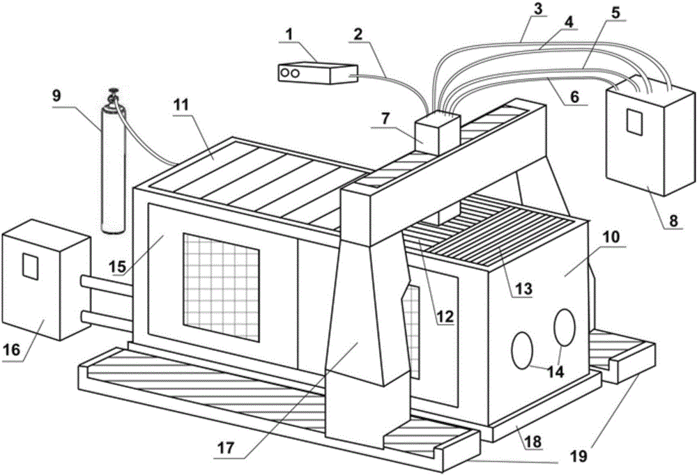
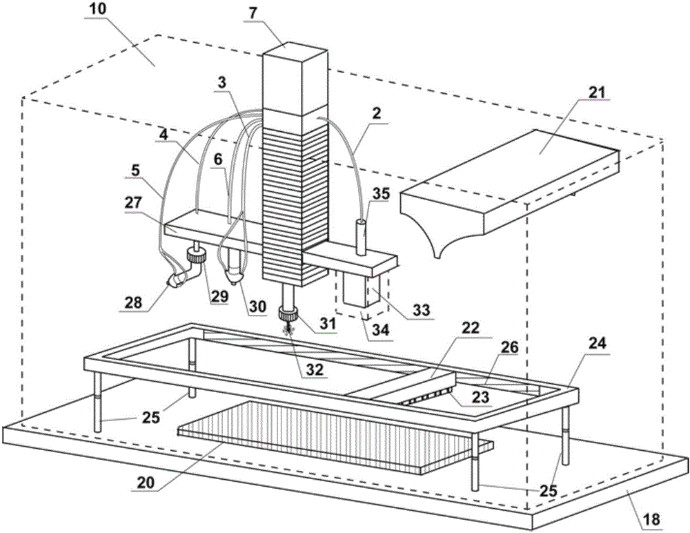
[0055] As shown in Figure 1, a laser additive manufacturing equipment provided by the example of the present invention includes a working cabin, a preset powder coating rapid prototyping component, a conformal cylinder setting and removal component, a machining component, a moving mechanism and a control system .
[0056] The working cabin includes a working cabin body 10, a protective gas source 9 and a dust removal system 16; the bottom of the working cabin body 10 is provided with a horizontal base 18, and the side is provided with a hatch 15 and a glove box joint 14; the protective gas source 9 and the dust removal system 16 is located outside the working cabin body 10; wherein, the protective gas source 9 is responsible for providing protective gas to the inside of the working cabin body 10; the inside of the dust removal system 16 is equipped with multi-stage filter elements and circulating fans, which are used to purify the inside of the working cabin body 10 due to high...
Embodiment 2
[0077] As shown in Figure 2, a laser additive manufacturing equipment provided by the example of the present invention includes a working cabin, a preset powder spreading rapid prototyping component, a conformal cylinder setting and removal component, a machining component, a moving mechanism and a control system .
[0078] The composition of the working cabin, the preset powder-spreading rapid prototyping component, the conformal cylinder setting and removal component, the mechanical processing component and the structure and function of the components contained in it are the same as those in Embodiment 1; wherein, the laser deposition and cutting host 8. The laser source 1, the protective gas source 9 and the dust removal system 16 are still located outside the working cabin body 10, the substrate 20, the powder storage chamber 21, the powder spreader 22, the scraper 23, the laser cutting head 28, the coaxial feeding nozzle 30, the mechanical The processing fixture 31 , cutt...
Embodiment 3
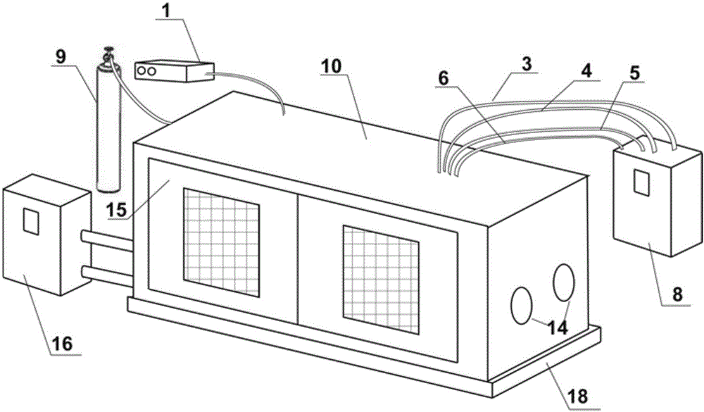
[0083] As shown in Figure 3, a laser additive manufacturing equipment provided by the example of the present invention includes a working cabin, a preset powder spreading rapid prototyping component, a conformal cylinder setting and removal component, a machining component, a moving mechanism and a control system .
[0084] The composition of the working cabin, the pre-set powder spreading rapid prototyping assembly, the mechanical processing assembly and the structure and function of the contained parts are the same as in Embodiment 1; wherein, the laser source 1, the protective gas source 9 and the dust removal system 16 are still in the working position. Outside the cabin 10, the substrate 20, the powder storage chamber 21, the powder spreader 22, the scraper 23, the machining fixture 31, the cutter 32, the scanning galvanometer 33, the dust cover 34, and the beam expander 35 are still located inside the working cabin 10 .
[0085] The follow-up cylinder setting and remova...
PUM
 Abstract
Description
Claims
Application Information
 - R&D
- Intellectual Property
- Life Sciences
- Materials
- Tech Scout
- Unparalleled Data Quality
- Higher Quality Content
- 60% Fewer Hallucinations
Browse by: Latest US Patents, China's latest patents, Technical Efficacy Thesaurus, Application Domain, Technology Topic, Popular Technical Reports.
© 2025 PatSnap. All rights reserved.Legal|Privacy policy|Modern Slavery Act Transparency Statement|Sitemap|About US| Contact US: help@patsnap.com


