
Method and device for preparing crack-free cladding layer through ultrasonic vibration-assisted laser cladding

An auxiliary laser and ultrasonic vibration technology, applied in the coating, metal material coating process and other directions, can solve the problems of increasing the heating process, the effect of vibration and stirring is not obvious, and the effect of stress homogenization in the micro-region of the molten pool is weakened, so as to improve the temperature. and stress distribution, ensuring synchronization and timeliness, and strengthening the effect of engineering application value

Inactive Publication Date: 2017-01-25
QINGDAO TECHNOLOGICAL UNIVERSITY
View PDF10 Cites 30 Cited by
  • Summary
  • Abstract
  • Description
  • Claims
  • Application Information

AI Technical Summary

Problems solved by technology

[0007] The research on the above new technology shows that although there is a certain inhibitory effect on the cracking of the laser cladding layer, each method has shortcomings. For example, the substrate preheating method increases the heating process, which reduces the production efficiency and deteriorates the working conditions. The laser cladding process of components is particularly obvious. At the same time, the surface of the parts is oxidized due to long-term heating, which weakens the performance of the cladding layer, resulting in a decrease in hardness, wear resistance and corrosion resistance; vibration elimination methods (mechanical vibration, ultrasonic vibration) in It is feasible in theory, but the actual situation is that the vibration source is applied to the bottom of the workpiece, so that the vibration of the workpiece affects the welding process, and the laser cladding area is a small area, and the vibration and stirring effect from the workpiece is not obvious, so that the molten pool The stress homogenization effect of the micro-area is greatly weakened, and the crack arrest effect of the cladding layer is not obvious

Method used


Image

  • Method and device for preparing crack-free cladding layer through ultrasonic vibration-assisted laser cladding
  • Method and device for preparing crack-free cladding layer through ultrasonic vibration-assisted laser cladding

Examples


Embodiment Construction

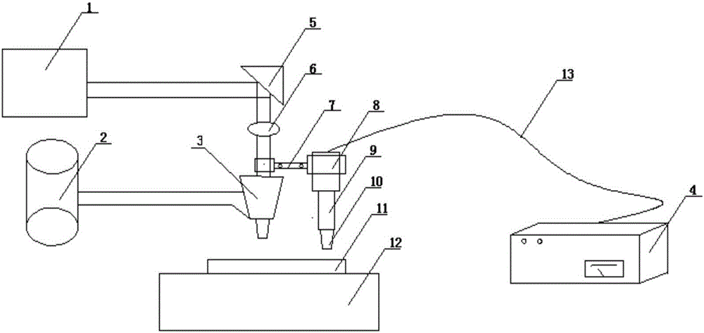
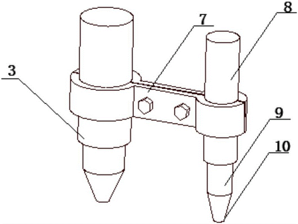
[0027] The present invention will be further described below in conjunction with the accompanying drawings and embodiments.

[0028] Such as figure 1 and figure 2 As shown, the device for preparing crack-free cladding layer by ultrasonic vibration-assisted laser cladding in the present invention includes a laser generator [1], a powder feeder [2], a laser head [3], an ultrasonic generator [4], Mirror [5], focusing lens [6], fixture [7], transducer [8], horn [9], vibrator [10], cladding layer [11], substrate [12] and cable [ 13]. Before the experiment, the substrate [12] was polished and the surface was wiped with acetone to remove impurities, the powder feeder [2] was connected to the laser generator [1] to prepare powder for the cladding process, and the ultrasonic generator [4] was connected with the cable [13]. Connect with the transducer [8], connect the horn [9] and vibrator [10] to the end of the transducer [8] at the same time to form a complete ultrasonic emission ...


PUM


Abstract

The invention discloses a method and a device for preparing a crack-free cladding layer through ultrasonic vibration-assisted laser cladding. Ultrasonic vibration aging is directly introduced into a molten pool micro-area, a direct cavitation effect, a mechanical effect and a heat effect of an ultrasonic wave are utilized for promoting the uniformity of a cladding layer stress field and the refining of grain tissues, and the generation of cracks is inhibited from the root; the ultrasonic wave can be directly acted on a molten pool, a promoting effect on temperature and stress distribution uniformity is higher than an overall vibration effect of a workpiece far away from the molten pool, and the three effects of the ultrasonic wave have a better stirring effect than that of an electromagnetic stirring elimination method, so that the new method has essential difference relative to previous methods, and has better superiority. By repeated experiments, an effect of refining the grain tissues can be achieved so as to prepare the crack-free cladding layer with a favorable surface appearance.

Description

technical field [0001] The invention relates to a method and a device for preparing a crack-free cladding layer by ultrasonic vibration-assisted laser cladding. Background technique [0002] Laser cladding technology is a new surface modification technology that has emerged with the development of high-power lasers. It places alloy powder on the surface of the substrate to be clad with different fillers, and uses laser as a heat source to rapidly melt the alloy powder. Melting, forming a coating with excellent performance on the surface of the body, so as to achieve the purpose of strengthening the surface of the workpiece. [0003] Laser cladding is a complex physical, chemical and metallurgical process, and it is a surface modification process that is very sensitive to cracks. The rapid heating of the laser beam makes the cladding layer completely melted, and the heat is too late to transfer, making the substrate temperature The temperature of the cladding layer is much l...

Claims


Application Information

Patent Timeline
IPC IPC(8): C23C24/10
CPCC23C24/10
Inventor 王玉玲张翔宇杨勇徐善瑞
Owner QINGDAO TECHNOLOGICAL UNIVERSITY
Learn More