Fabricated energy-saving wall body structure

A wall structure and prefabricated technology, which is applied to building components, building structures, passive houses, etc., can solve problems affecting the durability of walls, difficult installation, and large land occupation, so as to reduce greenhouse gas emissions and construction The installation speed is fast, which is beneficial to the anti-seismic effect of the building

Inactive Publication Date: 2017-01-25
XIAN UNIV OF SCI & TECH
View PDF5 Cites 0 Cited by
  • Summary
  • Abstract
  • Description
  • Claims
  • Application Information

AI Technical Summary

Problems solved by technology

[0003] 1. The prefabricated wall structure of concrete external wall panels is complex, heavy, unfavorable for earthquake resistance, high in cost, and requires a lot of land and formwork during prefabrication. Prefabrication and installation are inconvenient, and there are many thermal bridges, making it difficult to build low-energy buildings.
[0004] 2. Many prefabricated walls generally have the problem of many thermal bridges, poor energy saving and heat preservation
[0005] 3. The joint problem of the prefabricated wall panel of the prefabricated wall has not been solved
There is a project with this structure in Harbin. In winter, the joints are cold, ventilated, dew-condensed, and the indoor walls are dripping, moldy, and hairy, and cause the wooden floor to warp. Affect the durability of the wall and affect the comfort of living
This situation leads to the fear of adopting prefabricated thermal insulation walls in severe cold areas, which affects the process of residential industrialization and building energy conservation.
Or some use a prefabricated wall, and the outside is decorated with PVC plastic gussets or metal gussets to cover the gaps. Although no cracks can be seen, thermal bridges still exist at the joints, and there are hidden dangers of cold and ventilation at the joints. Still, the corrosion problem of steel columns and steel beams at the joints still exists
[0006] 4. There are frequent earthquakes in my country and the world, and the proportion of high-rise buildings in my country is very large. The existing prefabricated wall structure that adapts to the deformation of the main structure of the building is too complicated and expensive
Such as 1), Yu Yan's article "The connection structure of Japanese building wall panels", from the article and the accompanying drawings, it can be seen that the seismic structure of Japan's slidable prefabricated walls is too complicated
2), also like 08SJ110-2 and 08SG333 in the architectural standard design atlas "Prefabricated Concrete External Wall Panels". It can be seen from the drawings and descriptions that the structure of the slidable prefabricated wall is too complicated, and it is difficult to process prefabricated insulation panels. High difficulty, large amount of steel bars, heavy weight, large prefabrication area occupation, and high cost are not conducive to the popularization of prefabricated walls, and affect the safety of buildings against earthquakes and lateral movement of high-rise buildings
[0007] Traditional aerated concrete walls are built with aerated concrete blocks and then plastered, or for the installation of internal reinforcement aerated concrete wall panels and then plastered. Even if it is used in the south, the surface plaster is easy to bulge, crack, fall off, and seep. Quality problems such as leakage and cracking of joints, many wet operations on site, many thermal bridges, need to use thermal insulation mortar for insulation, and the earthquake resistance is not good
Air-entrained concrete has a high thermal conductivity and is not suitable for low-energy building applications in heating areas, especially not suitable for building energy conservation requirements in severe cold areas

Method used


Image

  • Fabricated energy-saving wall body structure

Examples


Embodiment Construction

[0020] The following will clearly and completely describe the technical solutions in the embodiments of the present invention with reference to the accompanying drawings in the embodiments of the present invention. Obviously, the described embodiments are only some, not all, embodiments of the present invention. Based on the embodiments of the present invention, all other embodiments obtained by persons of ordinary skill in the art without making creative efforts belong to the protection scope of the present invention.

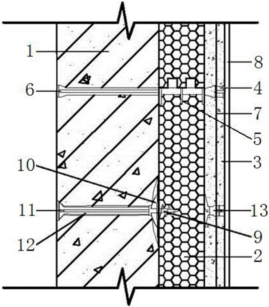
[0021] like figure 1 As mentioned above, the embodiment of the present invention provides a prefabricated energy-saving wall structure, which includes a base wall 1, an insulation layer 2, a protection layer 3 and an anchor bolt, and the anchor bolt passes through the protection layer 3 and the insulation layer 2, and the The protective layer 3 and the thermal insulation layer 2 are fixed to the base wall 1; the thermal insulation layer 2 is sandwiched between...


PUM


Abstract

The invention discloses a fabricated energy-saving wall body structure and relates to the technical field of wall bodies used for architectural engineering. The fabricated energy-saving wall body structure device comprises a base wall body, an insulating layer, a protective layer and an anchor bolt, wherein the anchor bolt passes through the protective layer and the insulating layer, and the protective layer, the insulating layer and the base wall body are fixed; the insulating layer is clamped between the base wall body and the protective layer; a first connecting piece is arranged between the base wall body and the insulating layer, the first connecting piece is connected with a locating jaw arranged in the insulating layer, a steel wire mesh suspending head is arranged between the insulating layer and the protective layer, one end of the steel wire mesh suspending head is connected with the locating jaw, and the other end of the steel wire mesh suspending head is connected with a steel wire mesh in the protective layer; and a locating disc is also arranged between the base wall body and the insulating layer, the locating disc is connected with a second connecting piece arranged in the base wall body, a fixed pin is arranged in the second connecting piece, a screw head is arranged at one end of the fixed pin, and the screw head is fastened in the insulating layer.

Description

technical field [0001] The invention relates to the technical field of a wall used in construction engineering, and more specifically relates to an assembled energy-saving wall structure. Background technique [0002] The current prefabricated wall technology has the following problems: [0003] 1. The prefabricated wall structure of concrete external wall panels is complex, heavy, unfavorable for earthquake resistance, high in cost, and requires a lot of land and formwork during prefabrication. Prefabrication and installation are inconvenient, and there are many thermal bridges, making it difficult to build low-energy buildings. [0004] 2. Many prefabricated walls generally have the problems of many thermal bridges and poor energy saving and heat preservation. 1) There are prefabricated light insulation wall panels installed in the frame structure in a fully inlaid type; 2) There are prefabricated light insulation wall panels installed in a semi-inlaid and half outsourcin...

Claims


Application Information

Patent Timeline
IPC IPC(8): E04B1/76
CPCE04B1/76E04B1/7629E04B1/7637Y02A30/00Y02B30/90
Inventor 邱继生
Owner XIAN UNIV OF SCI & TECH
Why Eureka
Try Eureka