Catalytic combustion treatment device

A catalytic combustion and treatment device technology, applied in the combustion method, combustion type, incinerator and other directions, can solve the problems of high temperature sintering failure of the catalyst, the volume of the catalytic burner is not used to the maximum, and the operating cost is high, so as to improve the volume utilization rate, The effect of improving treatment efficiency and purification quality, and reducing temperature

Inactive Publication Date: 2017-01-25
苏州聚贝机械设计有限公司
View PDF5 Cites 6 Cited by
  • Summary
  • Abstract
  • Description
  • Claims
  • Application Information

AI Technical Summary

Problems solved by technology

However, there are still the following problems. On the one hand, conventional catalytic burners mostly use a single catalytic method. Only low-temperature catalysis will lead to incomplete combustion of VOCs, and will also cause high-temperature sintering of catalysts placed behind to fail; only high-temperature catalysis needs to be heated to VOCs High temperature, waste of energy, and high operating costs; on the other hand, the catalyst bed and the combustion chamber are arranged up and down, the effective contact area between VOCs and the catalyst is small, and the volume of the catalytic burner has not been utilized to the maximum, which needs to be improved

Method used


Image

  • Catalytic combustion treatment device

Examples


Embodiment

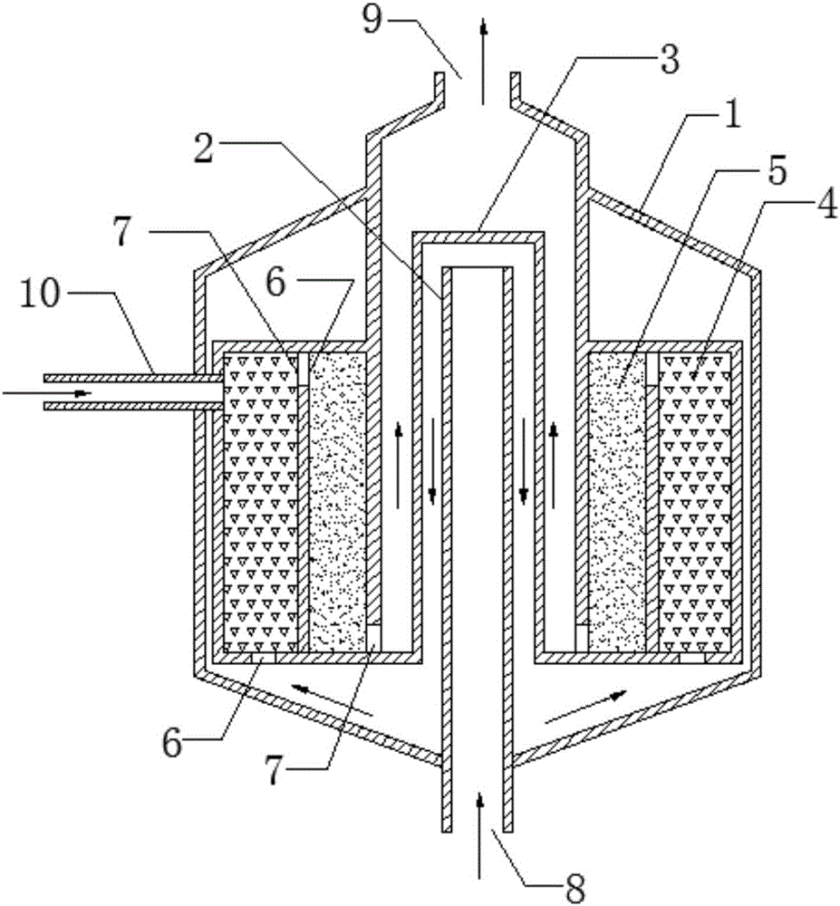
[0020] Example: A catalytic combustion treatment device, such as figure 1 As shown, a catalytic combustion processor 1 is included. The catalytic combustion processor 1 includes a central pipe 2, a central heat exchange chamber 3, a low-temperature catalyst bed 4, a high-temperature catalyst bed 5, an exhaust gas inlet 8 and a purified gas outlet 9. The central heat exchange cavity 3 is located at the center of the catalytic combustion processor 1, and a central pipe 2 is provided at the center of the central heat exchange cavity 3. The exhaust gas inlet 8 communicates with each other, the high temperature catalyst bed 5 is arranged on the outside of the central heat exchange cavity 3, and the low temperature catalyst bed 4 is arranged on the outside of the high temperature catalyst bed 5; The lower part is provided with an air inlet 6, the upper part is provided with an air outlet 7, the upper part of the high temperature catalyst bed 5 is provided with an air inlet 6, and the...


PUM


Abstract

The invention discloses a catalytic combustion treatment device. The catalytic combustion treatment device comprises a catalytic combustion treater and an oxygen generator, wherein the catalytic combustion treater comprises a central pipeline, a central heat exchange cavity, a low-temperature catalyst bed layer, a high-temperature catalyst bed layer, a waste gas inlet and a purified air outlet. In the catalytic combustion treatment device, the low-temperature catalyst bed layer is taken as an outer layer, the high-temperature catalyst bed layer is taken as an inner layer, and the catalyst bed layers are arranged annularly, so that the utilization rate of a catalytic combustor is increased greatly, VOCs (Volatile Organic Compounds) perform full contact reaction with a catalyst, the treatment efficiency is increased, and the purifying quality is improved; meanwhile, the central heat exchange cavity can be used for recycling energy of high-temperature gas, so that the catalytic combustion treatment device is environmental-friendly and saves energy, the temperature of exhausted gas is lowered, and safety and stability are achieved.

Description

Technical field [0001] The invention belongs to the technical field of waste gas treatment, and particularly relates to a catalytic combustion treatment device for collecting organic waste gas in spray areas of flow production lines in various solvent-based surface coatings, furniture industry and printing industry. Background technique [0002] Volatile Organic Compounds (VOCs) are compounds with a boiling point of 50°C-250°C according to the definition of the World Health Organization, a saturated vapor pressure exceeding 133.32Pa at room temperature, and a class of organic compounds that exist in the air in the form of vapor at room temperature. The main components of VOCs are: hydrocarbons, halogenated hydrocarbons, oxygenated hydrocarbons and nitrogenous hydrocarbons, including benzene series, organic chlorides, Freon series, organic ketones, amines, alcohols, ethers, esters, acids and petroleum hydrocarbon compounds. The hazards of volatile VOCs are obvious. The main effect...

Claims


Application Information

Patent Timeline
Patent Type & Authority Applications(China)
IPC IPC(8): F23G7/07
CPCF23G7/07F23G2202/60F23G2209/14Y02A50/20
Inventor 邹诚杰
Owner 苏州聚贝机械设计有限公司
Why Eureka
Try Eureka