Constant volume bomb for diesel spraying and burning visualization experiment

A constant-volume bomb and diesel technology, which is used in internal combustion engine testing, engine testing, and machine/structural component testing. High pressure requirements are difficult and other problems to achieve the effect of reducing local stress phenomenon, light weight, and reducing experimental cost

Active Publication Date: 2017-01-25
HARBIN ENG UNIV
View PDF5 Cites 17 Cited by
  • Summary
  • Abstract
  • Description
  • Claims
  • Application Information

AI Technical Summary

Problems solved by technology

Chinese patent CN 101943097 A discloses a constant-volume projectile for spray testing, which has openings in the circumferential direction of the projectile, and each opening position is fixed with a piece of quartz glass by a quartz flange, and the upper cover of the projectile body, the lower cover of the projectile body and the projectile body pass through bolts Connected together, the circumferential opening of this invention can flexibly arrange the test optical path and has universal applicability, but the shape of the test cavity inside the constant volume bomb is irregular, which cannot meet the requirements of the test for heat dissipation calculation
Chinese patent CN 103926196 A discloses a spherical multifunctional constant volume bomb, which is shaped like a sphere and has more than two visualization windows. It is more difficult to meet the high pressure requirements of the experiment
Deng Peng and others f

Method used


Image

  • Constant volume bomb for diesel spraying and burning visualization experiment
  • Constant volume bomb for diesel spraying and burning visualization experiment
  • Constant volume bomb for diesel spraying and burning visualization experiment

Examples


Example Embodiment

[0018] The present invention will be further described in detail below in conjunction with the drawings and specific embodiments.

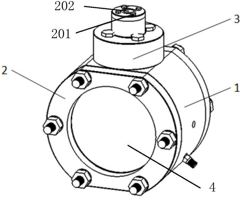
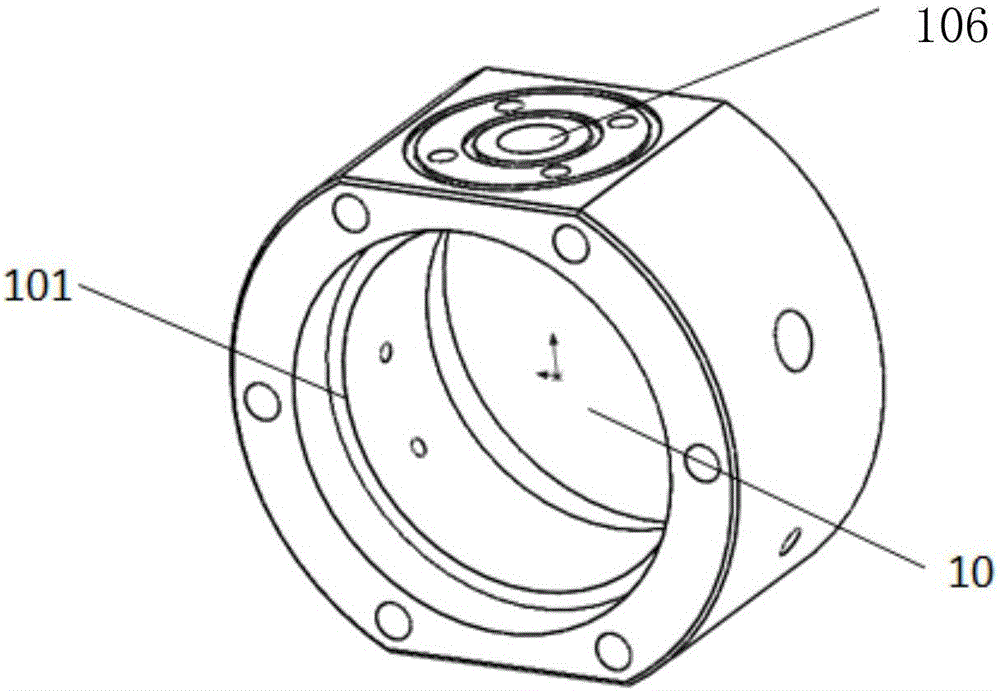
[0019] The present invention provides a constant volume projectile for the visual test of diesel spray and combustion. figure 1 As shown, it mainly includes: a constant volume bomb body 1, a sealing cover 2, a top cover 3, and a quartz glass window 4. The body 1 of the constant volume bomb adopts a circular pie-shaped structure with a hollow inside to form a visual test area 10. Open window holes on both sides of the circular pie and process the same size annular installation groove to install the window assembly. The installation groove has a diameter of 186mm and a depth. The thickness of the quartz glass is about 0.75 times, and the quartz glass 4 is fixed with a metal sealing cover 2 for sealing. The two sealed end faces bear the main sealing pressure; the upper and lower end faces of the fixed volume bomb body 1 are flat, and the upper end face i...


PUM


Abstract

The invention provides a constant volume bomb for a diesel spraying and burning visualization experiment. The constant volume bomb comprises a constant volume bomb body. The constant volume bomb body uses the circular-cake-shaped structure, the interior is hollow and used for forming the visualization experiment area, two sides of the circular cake are opened with visualization window holes and the end faces of the windows are pressed by sealing cover plates for sealing. The quartz glass is clamped between the body and the sealing cover plates. The upper end face is opened with a positioning hole for an oil sprayer installing base, and the unique design is suitable for use of various oil sprayers. The lower end face is opened with a positioning threaded hole for fixing the position of the constant volume bomb. The constant volume bomb body is radially opened with various installing through holes for installing various data collecting devices. The visualization spraying constant volume napalm bomb has the characteristics of simple structure, wide experiment area and transparent light path, and is capable of observing and measuring the spraying and burning processes through cooperating the schlieren method and the laser-induced fluorescence technology, remarkably improving the experiment efficiency, performing the spraying feature test to different oil sprayers and improving the adaptability of the spraying constant volume test bomb.

Description

technical field [0001] The invention relates to a constant-volume projectile used for diesel spray and combustion visualization tests, and belongs to the technical field of internal combustion engines. Background technique [0002] Various thermal parameters (pressure, temperature, ignition parameters) of the diesel engine have a significant impact on the combustion process of the diesel engine. Simulating the combustion performance of diesel engines under various conditions is of great significance for the development of engine combustion systems. The constant volume bomb is an engine combustion simulation experimental device, which can efficiently simulate the temperature and pressure of the diesel engine at each crank angle and the combustion situation in the combustion chamber, and can accurately control a variety of thermodynamic parameters to quantitatively study the impact of each parameter on the spray characteristics of the engine injector. Impact. [0003] As the...

Claims


Application Information

Patent Timeline
IPC IPC(8): G01M15/02G01M15/04
CPCG01M15/02G01M15/04
Inventor 刘龙高兴家苟金彭雁李文辉王忠巍刘友马修真
Owner HARBIN ENG UNIV
Why Eureka
Try Eureka