
Broadband dual circularly polarized planar waveguide array antenna

A dual circular polarization and planar waveguide technology, which is applied in antennas, antenna arrays, electrical components, etc., can solve the problems that the circular polarization synthesis method and estimated performance are not given, and the implementation is difficult, achieving axial ratio and isolation The effect of stable performance, high broadband response, and compact structure

Active Publication Date: 2017-01-25
UNIV OF ELECTRONICS SCI & TECH OF CHINA
View PDF6 Cites 34 Cited by
  • Summary
  • Abstract
  • Description
  • Claims
  • Application Information

AI Technical Summary

Problems solved by technology

[0004] Literature "D.Kim, M. Zhang, J. Hirokawa, and M. Ando, ​​"Design and fabrication of adu al-polarization waveguide slot array antenna with high isolation," IEEE Transactions on Antennas and Propagation, vol.62, no. 6, pp.3019-3027, Jun.2014." proposed a dual-polarized array antenna with a full waveguide structure, which was processed by molecular diffusion welding technology to realize a dual-polarized array configuration. The antenna radiation unit is Cross slot, slot coupling feed, antenna working bandwidth is 11%; this kind of full waveguide array antenna has high total efficiency due to no dielectric loss, which is greater than 70% in the whole frequency band, but the article does not give the synthesis method of circular polarization and estimated performance
[0005] In summary, high-performance dual circularly polarized array antennas are rarely seen in public literature, especially for the design of millimeter-wave applications. a great challenge for the world

Method used


Image

  • Broadband dual circularly polarized planar waveguide array antenna
  • Broadband dual circularly polarized planar waveguide array antenna
  • Broadband dual circularly polarized planar waveguide array antenna

Examples


Embodiment Construction

[0022] The present invention will be described in further detail below in conjunction with the accompanying drawings and embodiments.

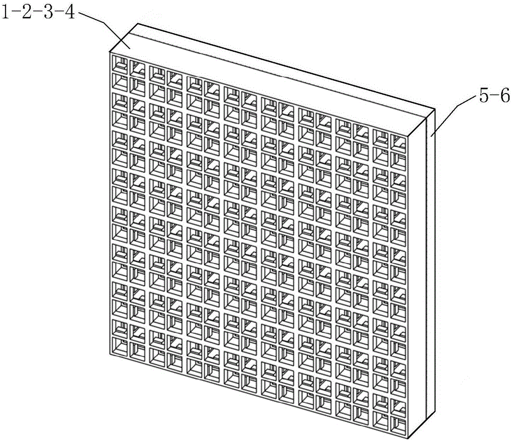
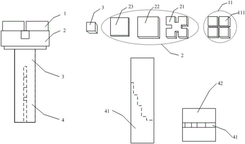
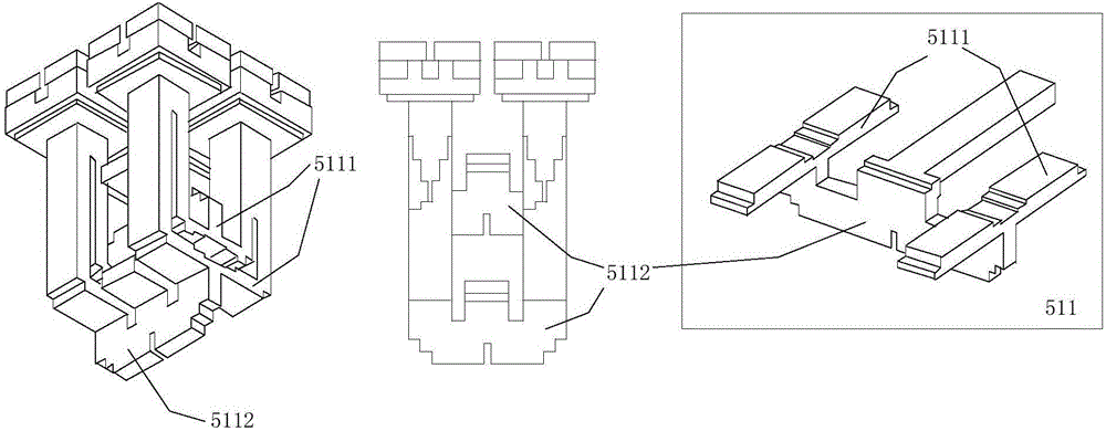
[0023] This embodiment provides a 16×16-element broadband dual circularly polarized planar waveguide array antenna, the structure of which is as follows Figure 1~4 As shown, it includes radiation aperture 1, resonant cavity 2, feeding square waveguide 3, circular polarizer 4, dual-polarized feeding network 5 and standard waveguide interface transition 6 stacked sequentially from top to bottom;

[0024] Such as figure 1 As shown, the radiation aperture 1 is a waveguide aperture array, which is composed of several 2×2 element sub-arrays 11 arranged in an array. Arranged in an array, each square waveguide radiation port 111 has the same size and the same adjacent spacing, and the side length of the square waveguide radiation port 111 is greater than λ l / 2, less than λ h ,λ l and lambda h are the wavelengths of the lowest operating frequenc...


PUM


Abstract

The invention belongs to the field of design and manufacturing of millimeter wave antennas and provides a broadband dual circularly polarized planar waveguide array antenna. The antenna comprises a radiation aperture, a resonant cavity, a feed square waveguide, a circular polarizer, a dual polarization feed network and a standard waveguide interface which are sequentially stacked from top to bottom, wherein the radiation aperture consists of multiple 2*2 atomic arrays arranged in an array; the resonant cavity consists of a square ridge waveguide resonant cavity, a first square waveguide resonant cavity and a second square waveguide resonant cavity which are sequentially stacked from top to bottom; the circular polarizer is formed by inserting a stepped metal membrane into the square waveguide in a center loading manner; the dual polarization feed network consists of a left-hand circular polarization feed network and a right-hand circular polarization feed network; the standard waveguide interface comprises two output ports, namely, a left-hand circular polarization interface and a right-hand circular polarization interface. The broadband dual circularly polarized planar waveguide array antenna with high gain and efficiency is realized.

Description

technical field [0001] The invention belongs to the technical field of design and manufacture of millimeter-wave antennas, and in particular relates to a wide-band, high-efficiency, double-circularly polarized millimeter-wave planar waveguide array antenna. Background technique [0002] Dual-polarized antennas are widely used in frequency division multiplexing systems, while circularly polarized antennas have the characteristics of anti-multipath and easy polarization matching. Therefore, in the new generation of satellite communication systems (such as Ka-band satellite communication), dual The working mode of circular polarization is widely used; at the millimeter wave frequency, the atmospheric attenuation is serious, so it is necessary to use a high-gain antenna to ensure the effective range, array synthesis is an important way to achieve high gain; based on the above reasons, high-performance Dual circularly polarized array antenna is a hotspot in the field of antenna r...

Claims


Application Information

Patent Timeline
IPC IPC(8): H01Q21/00H01Q15/24
CPCH01Q15/24H01Q21/00
Inventor 程钰间吴杰王洪斌郑雨阳樊勇张波林先其张永鸿赵明华
Owner UNIV OF ELECTRONICS SCI & TECH OF CHINA
Learn More