
Boiler waste heat recycling and steam temperature control system

A steam temperature control, boiler technology, applied in the direction of superheated temperature control, steam superheating, steam generation, etc., can solve the problems of insensitive adjustment of the main steam temperature of the boiler, large temperature difference, insensitive adjustment, etc., to solve the problem of superheater explosion Tube and desuperheater damage, life improvement effect

Inactive Publication Date: 2017-02-08
WUXI XIANGLONG GLOBAL TECH CO LTD
View PDF5 Cites 2 Cited by
  • Summary
  • Abstract
  • Description
  • Claims
  • Application Information

AI Technical Summary

Problems solved by technology

[0006] 1. Water spray desuperheating method is used to control the boiler steam temperature. Boilers using water spray desuperheating method are likely to cause weld cracks in the desuperheater header and cracks on the inner wall of the pipe.
The reason is that the temperature difference between the feed water temperature (104°C) used for boiler steam desuperheating and the steam temperature after desuperheating (540°C) is too large, and the excessive temperature difference can also cause problems such as superheater tube burst
[0007] 2. The surface desuperheating method uses all the desuperheating water to control the temperature of the main steam through the surface desuperheater. The surface desuperheating is generally used in small boilers. The main disadvantage is that the temperature adjustment of the main steam of the boiler is not sensitive
[0008] 3. The self-made condensing water spray desuperheating method also has problems such as insensitive adjustment, large temperature difference, and superheater tube burst.

Method used


Image

  • Boiler waste heat recycling and steam temperature control system
  • Boiler waste heat recycling and steam temperature control system
  • Boiler waste heat recycling and steam temperature control system

Examples


Embodiment Construction

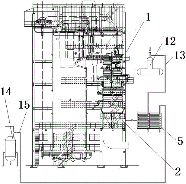
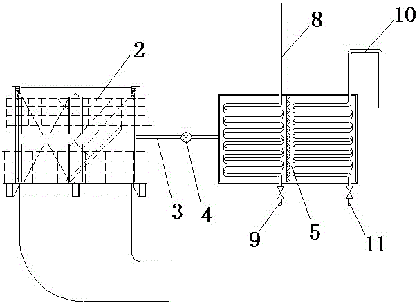
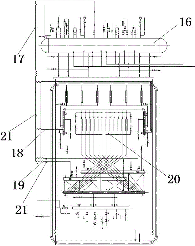
[0020] see Figure 1 to Figure 3 , the present invention relates to a boiler waste heat recovery and steam temperature control system, comprising a boiler 1, the boiler 1 is equipped with a plurality of air preheaters 2, wherein the air inlet pipe 3 of each air preheater 2 is connected with The fan 4 is connected, and the front end of the fan 4 is provided with a heat exchange device 5, and the heat exchange device 5 is provided with a cold air inlet 6, a hot air outlet 7, a first hot water inlet 8, a first cold water outlet 9, and a second hot water inlet 10. The second cold water outlet 11. There are two water pipes inside the heat exchange device 5, which are respectively connected with the first hot water inlet 8 and the first cold water outlet 9, and with the second hot water inlet 10 and the second cold water outlet 11. The first hot water inlet 8 is connected with the emptying pipe 13 on the deaerator 12 of the boiler 1, and the second hot water inlet 10 is connected wi...


PUM


Abstract

The invention relates to a boiler waste heat recycling and steam temperature control system. By means of the boiler waste heat recycling and steam temperature control system, the temperature of air entering an air preheater can be raised, and cold air is prevented from corroding an air inlet pipe of the air preheater; meanwhile, condensed water of an evacuated steam source of a deaerator can be recycled effectively, waste of energy and resources is avoided, and environmental pollution is avoided; in addition, a heat exchange device is mounted in front of an air feeder, and the effect of suppressing noise of a draught fan is achieved; and meanwhile, the pressure difference between saturated steam and superheated steam of a steam pocket is utilized, the saturated steam is adopted for substituting desuperheating water to lower the temperature of a boiler, thus the service life of the boiler can be greatly prolonged, and the problems that pipes of a superheater burst and a desuperheater is damaged due to the fact that the temperature difference of the desuperheater is large are effectively solved.

Description

technical field [0001] The invention relates to a waste heat recycling system and a steam temperature control system, belonging to the technical field of energy saving and environmental protection. Background technique [0002] Power plant boilers, industrial boilers, and industrial furnaces need to pass cold air into the air preheater through a fan. The air preheater heats the cold air and sends it to the boiler for use. Exposure to cold air causes dew condensation corrosion, which will be corroded in less than 2-3 years, resulting in air leakage from the air preheater, resulting in frequent replacement of the air preheater and high maintenance costs. The device, and the installation position is high, it is inconvenient to disassemble and repair, and the maintenance time is long. [0003] At the same time, power plant boilers, industrial boilers, and industrial furnaces will produce waste gas, waste water, waste steam, waste residue, etc. during industrial production, whic...

Claims


Application Information

Patent Timeline
IPC IPC(8): F23L15/00F22G5/14
CPCF22G5/14F23L15/00Y02E20/34
Inventor 陆兵赵志龙戚云峰
Owner WUXI XIANGLONG GLOBAL TECH CO LTD
Learn More