Flue-gas purifying system for boiler

A flue gas purification system and flue gas technology, applied in gas treatment, chemical instruments and methods, dispersed particle filtration, etc., can solve problems affecting denitrification reaction efficiency, equipment corrosion, air preheater 2' blockage, etc., to achieve improved The effect of denitrification efficiency and guaranteed service life

Pending Publication Date: 2017-02-15
FUJIAN LONGKING
View PDF5 Cites 3 Cited by
  • Summary
  • Abstract
  • Description
  • Claims
  • Application Information

AI Technical Summary

Problems solved by technology

[0004] When the flue gas flows through the above-mentioned flue gas purification system, the denitration reaction is carried out first, and then the dust removal and desulfurization reactions are carried out. This process has the following disadvantages: the catalyst in the denitrification reactor 3' will make the SO in the flue gas 2 is oxidized to SO 3 , SO 3 with escaped NH 3 Generate NH 4 HSO 4 and (NH 4 ) 2 SO 4 , NH 4 HSO 4 It is corrosive and viscous, which can lead to blockage of the air preheater 2' and corrosion of subsequent equipment. At the same time, it can also cause catalyst poisoning and affect the efficiency of denitrification reaction

Method used


Image

  • Flue-gas purifying system for boiler
  • Flue-gas purifying system for boiler

Examples


Embodiment Construction

[0026] In order to enable those skilled in the art to better understand the technical solutions of the present invention, the present invention will be further described in detail below in conjunction with the accompanying drawings and specific embodiments.

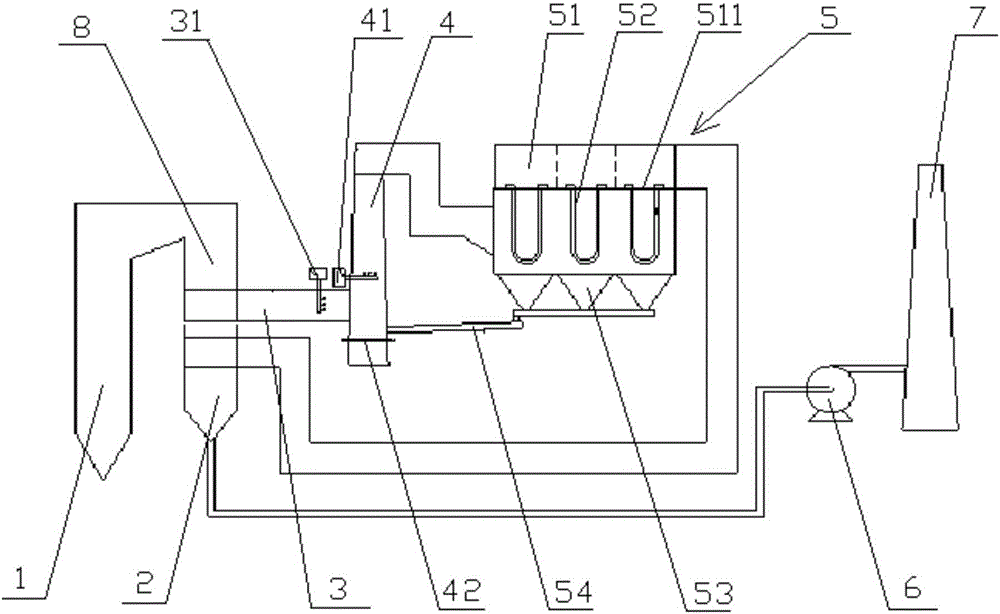
[0027] Please refer to the attached figure 2 , figure 2 It is a schematic structural diagram of the flue gas purification system of the boiler provided by the present invention.

[0028] In a specific embodiment, the present invention provides a flue gas purification system of a boiler 1, such as figure 2 As shown, the high-temperature flue gas produced by the combustion of the boiler 1 is discharged from the economizer 8 and enters the intake flue 3. The flue gas purification system also includes a mixed reaction tower 4 and a dust filter 5 that communicate with each other, wherein, The mixed reaction tower 4 is used for the desulfurization process of the flue gas, and the dust nitrification filter 5 is used for the...


PUM

PropertyMeasurementUnit
pore sizeaaaaaaaaaa
pore sizeaaaaaaaaaa

Abstract

The invention discloses a flue-gas purifying system for a boiler. The flue-gas purifying system comprises a mixed reaction tower and a dust and nitrate filter which are communicated. The flue-gas purifying system is characterized in that flue gas is firstly desulfurized by the mixed reaction tower, then is dedusted and denitrified by the dust and nitrate filter, and the flue-gas flow is firstly dedusted and then is denitrified when passing through the dust and nitrate filter. Therefore, the flue gas is purified according to the sequence of desulfurization, dedusting and denitrification, so that the generation of NH4HSO4 in denitrification of the flue gas is avoided, further ash blocking of an air preheater and corrosion of equipment are avoided, and the catalyst poisoning caused by alkali metal and dust particles in the flue gas is avoided to guarantee the efficiency of denitrifying reaction.

Description

technical field [0001] The invention relates to the technical field of flue gas purification, in particular to a flue gas purification system for a boiler. Background technique [0002] Pollutants emitted by industrial boilers mainly include soot, sulfur oxides, nitrogen oxides, etc. Among them, the existence of sulfur oxides will cause corrosion of power station equipment, increase of flue gas opacity, formation of acid rain, etc., and will be discharged into the air It can also cause respiratory diseases in humans. [0003] At present, commonly used industrial boiler flue gas treatment systems such as figure 1 as shown, figure 1 It is a structural schematic diagram of the flue gas purification system in the prior art, and its flue gas treatment process route is: after the flue gas from the boiler 1' is discharged from the economizer 8', it enters the denitrification reactor 3', and the ammonia water injector 31' sprays the ammonia water Into the denitrification reactor ...

Claims


Application Information

Patent Timeline
Patent Type & Authority Applications(China)
IPC IPC(8): B01D53/78B01D53/83B01D53/50B01D53/86B01D53/56B01D46/24
CPCB01D46/2411B01D53/502B01D53/508B01D53/8631B01D2258/0283B01D2259/124B01D2259/128
Inventor 黄星寇向上刘颖赖栋文林荷王妨
Owner FUJIAN LONGKING
Why Eureka
Try Eureka