
Low-temperature exhaust heat concentration system and method utilizing wastewater of thermal power plant

A concentration system, low-temperature waste heat technology, applied in the direction of gaseous effluent wastewater treatment, etc., can solve the problems of high flue gas temperature, flue evaporation stroke, shutdown or demolition, waste water damage, etc., to achieve a small footprint and easy operation Reliable, low energy consumption for operation

Pending Publication Date: 2017-02-22
四川苏源环保工程有限公司
View PDF9 Cites 4 Cited by
  • Summary
  • Abstract
  • Description
  • Claims
  • Application Information

AI Technical Summary

Problems solved by technology

[0010] Although this evaporation method has a simple system and low investment and energy consumption, it has high requirements on the temperature of the flue gas and the evaporation process in the flue; if the evaporation conditions are not met, the waste water will enter the electrostatic precipitator in liquid form, etc. There is a great risk of damage to downstream equipment. A small number of power plants in China have done pilot installations, but they have basically been shut down or dismantled now.

Method used


Image

  • Low-temperature exhaust heat concentration system and method utilizing wastewater of thermal power plant
  • Low-temperature exhaust heat concentration system and method utilizing wastewater of thermal power plant
  • Low-temperature exhaust heat concentration system and method utilizing wastewater of thermal power plant

Examples


Embodiment 1

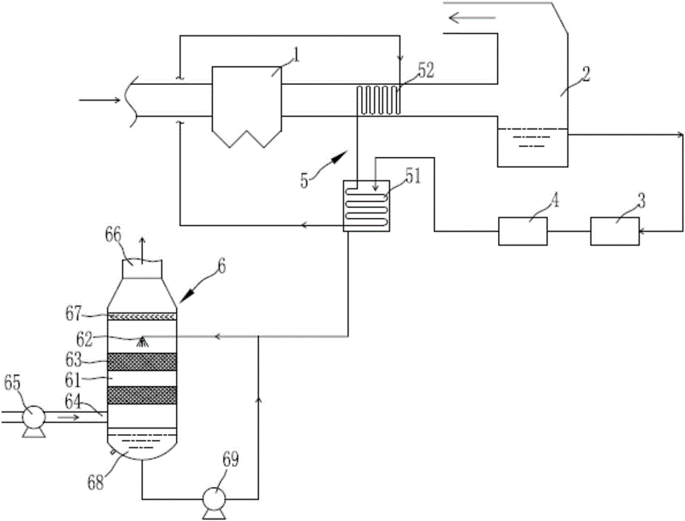
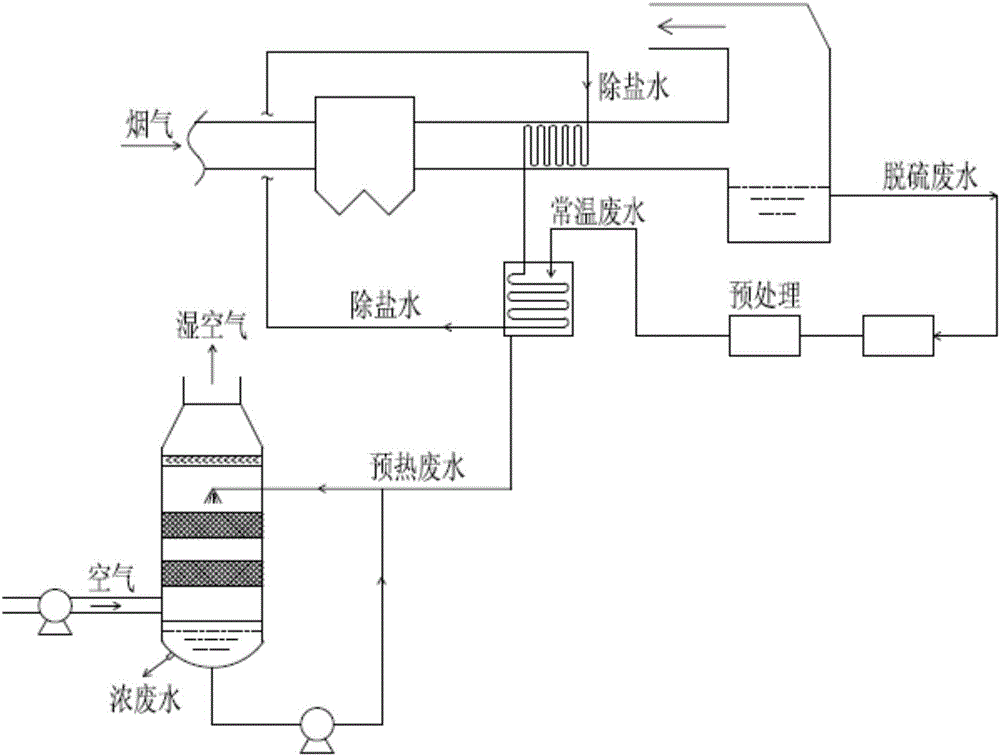
[0040] Such as figure 1 and figure 2 As shown, the low-temperature waste heat concentration system for thermal power plant waste water includes a dust collector 1 (electrical dust collector can be used) for dedusting the flue gas discharged from the boiler, a desulfurization absorption tower 2 for desulfurizing the dust-removed flue gas, and a storage desulfurization absorption tower. The waste water collecting tank 3 of the waste water produced by the tower 2 and the pretreatment device 4 for pretreatment of the waste water in the waste water collecting tank 3; The equipment implements its corresponding functions, so I won’t go into details here; it also includes:

[0041] Wastewater preheating device 5, which utilizes the flue gas heat in the flue between the dust remover 1 and the desulfurization absorption tower 2 to preheat the pretreated waste water; in this embodiment, the waste water preheating device 5 includes the The wastewater preheater 51 downstream of the pret...

Embodiment 2

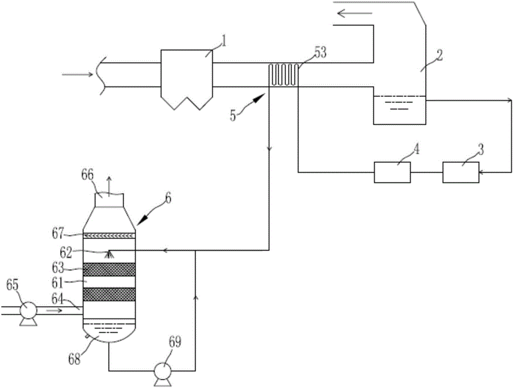
[0049] Such as image 3 and Figure 4 As shown, the low-temperature waste heat concentration system for thermal power plant waste water in this embodiment is basically the same in structure and principle as in Embodiment 1, and the similarities will not be repeated here. The only difference is:

[0050] In this embodiment, the wastewater preheating device 5 adopts a direct preheating method, that is, the wastewater after pretreatment such as neutralization, precipitation, flocculation, and clarification directly flows through and is arranged between the dust collector 1 and the desulfurization absorption tower 2 The coil 53 in the flue is preheated, and then enters the evaporative concentration tower for evaporative concentration, but this method needs to strictly control the preheating temperature (40-50°C) of the waste water. If the preheating temperature is too high, the Ca( HCO 3 ) 2 and Mg(HCO 3 ) 2 The thermal decomposition in the coil produces serious Ca and Mg ion...


PUM


Abstract

The invention belongs to the technical field of wastewater treatment of a thermal power plant and particularly relates to a low-temperature exhaust heat concentration system and method utilizing wastewater of a thermal power plant. The system comprises a dust removal device, a desulfurizing absorption tower, a wastewater collecting tank, a pretreatment device, a wastewater preheating device and an evaporation concentration tower, wherein the wastewater preheating device preheats pretreated wastewater by use of flue gas heat in a flue between the dust removal device and the desulfurizing absorption tower; the evaporation concentration tower is used for evaporating the preheated wastewater at the low temperature and comprises a tower body, an atomizing device connected with a wastewater outlet of the wastewater preheating device is arranged in the tower body, and multiple filler layers are arranged below the atomizing device and in the tower body; an air inlet is formed in the lower part of the tower body and connected with a blower, and an air outlet is formed in the upper part of the tower body; a wastewater concentration circulating system is arranged at the bottom of the tower body. The system is simple in overall design, reliable to operate, low in operation energy consumption and lower in investment cost and occupies a small area.

Description

technical field [0001] The invention belongs to the technical field of thermal power plant wastewater treatment, and in particular relates to a thermal power plant wastewater low-temperature waste heat concentration system and a concentration method. Background technique [0002] Limestone-gypsum wet desulfurization technology is currently the most widely used flue gas desulfurization technology in thermal power plants. During the operation of the desulfurization device, a large amount of wastewater is regularly discharged, that is, desulfurization wastewater. The wastewater has the characteristics of high concentration of suspended solids, high concentration of inorganic salts and heavy metal ions. [0003] Traditional desulfurization wastewater treatment process chemical dosing method: traditional chemical treatment methods of neutralization, precipitation, flocculation, concentration and clarification are often used for treatment. Although it can reduce the content of he...

Claims


Application Information

Patent Timeline
IPC IPC(8): C02F1/16C02F103/18
CPCC02F1/16C02F2103/18
Inventor 代旭东曲守信赵金田健范玺
Owner 四川苏源环保工程有限公司
Learn More