
Method for solving engine piston scuffing
A technology for engines and pistons, which is applied in the field of material surface modification, which can solve problems such as temperature rise, piston heat load increase, piston high-temperature strength and load-bearing capacity reduction, etc., and achieve the effect of good bonding force and enhanced peel strength
- Summary
- Abstract
- Description
- Claims
- Application Information
AI Technical Summary
Problems solved by technology
Method used
Image

Examples
Embodiment 1
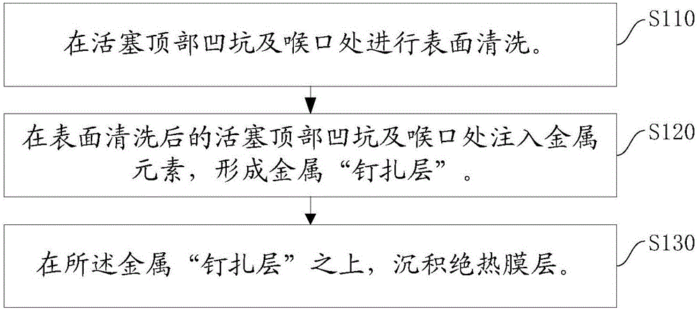
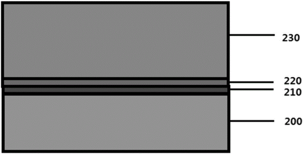
[0036] In order to solve the problem of piston scuffing in the current engine, this embodiment provides a method to solve the problem of engine piston scuffing, depositing an insulating film on the pit and throat on the top of the piston to prevent the heat of the combustion chamber from going down to the piston. The conduction of key components solves the problem of piston scuffing. figure 1 A schematic flow chart of depositing a thermal insulation film layer at the top pit and throat of the piston provided by the embodiment of the present invention, figure 2 It is a schematic diagram of the structure of the heat insulating film layer provided by the embodiment of the present invention. Such as figure 1 As shown, the method includes:
[0037] S110, perform surface cleaning on the pit and throat on the top of the piston.
[0038] In one example, metal ion beams are used to clean the surface of the piston top pit and throat to form a base layer. Preferably, a magnetic filt...
Embodiment 2
[0047] Deposit Al on piston top pit and throat 2 o 3 Insulation film layer. The implementation steps are as follows:
[0048] S110, preparation of metal cleaning layer 210
[0049] Al deposition: fix the piston base material 200 on the sample stage, rotate the sample to the deposition target position, and start deposition, that is, clean the surface of the piston base material 200 to obtain the metal cleaning layer 210 . The deposition arc source is an Al arc source with a purity of 99%, and the deposition conditions are: vacuum degree 1×10 -3 -6×10 -3 Pa, deposition arc current: 100-120A, magnetic field current: 1.4-2.4A, arc current: 380-440mA, negative pressure: 400V-1000V, duty cycle 50%-100%, deposition time 3-60S, magnetic filter pipeline Filtered at 90°.
[0050] S120, preparation of metal "pinning layer" 220:
[0051] Implantation: Rotate to the implantation target position to start implantation, that is, implant metal ions on the metal cleaning layer 210 to obt...
Embodiment 3
[0055] Deposit TiC-DLC thermal insulation layer on the top pit and throat of the piston. The implementation steps are as follows:
[0056] S110, preparation of metal cleaning layer 210:
[0057] Ti deposition: fix the piston substrate 200 on the sample stage, rotate the sample to the deposition target position and start deposition. The deposition arc source is a Ti arc source with a purity of 99%, and the deposition conditions are: vacuum degree 1×10 -3 -6×10 -3 Pa, deposition arc current: 100-110A, magnetic field current: 1.4-2.4A, arc current: 380-440mA, negative pressure: -400V-1000V, duty cycle 50%-100%, deposition time 3-60S, magnetic filtration The piping is 90° filtered.
[0058] S120, preparation of metal "pinning layer" 220:
[0059] Injection: Turn to the injection target position to start injection. The implanted ion source is pure Ti with a purity of 99.9%, and the implantation conditions are: vacuum degree 1×10 -3 -6×10 -3 Pa, injection arc voltage: 50-70V...
PUM
| Property | Measurement | Unit |
|---|---|---|
| thickness | aaaaa | aaaaa |
| microhardness | aaaaa | aaaaa |
| microhardness | aaaaa | aaaaa |
Abstract
Description
Claims
Application Information