A millimeter wave reconfigurable antenna

A technology for reconstructing antennas and millimeter waves, applied in antennas, waveguide horns, electrical components, etc., can solve the problems of difficult to achieve high-efficiency antenna development, large PIN diode loss, and difficult application of large-diameter antennas, etc., to achieve light weight, The effect of low antenna loss and simple structure

Active Publication Date: 2019-08-13
UNIV OF ELECTRONICS SCI & TECH OF CHINA
View PDF8 Cites 0 Cited by
  • Summary
  • Abstract
  • Description
  • Claims
  • Application Information

AI Technical Summary

Problems solved by technology

Since each unit structure of the antenna needs to be loaded with a diode, the structure of the antenna is more complicated, and it is difficult to be applied to a large-aperture antenna
At the same time, in the millimeter wave band, the loss of the PIN diode is relatively large, and it is difficult to realize the development of high-efficiency antennas.

Method used


Image

  • A millimeter wave reconfigurable antenna
  • A millimeter wave reconfigurable antenna
  • A millimeter wave reconfigurable antenna

Examples


Embodiment 1

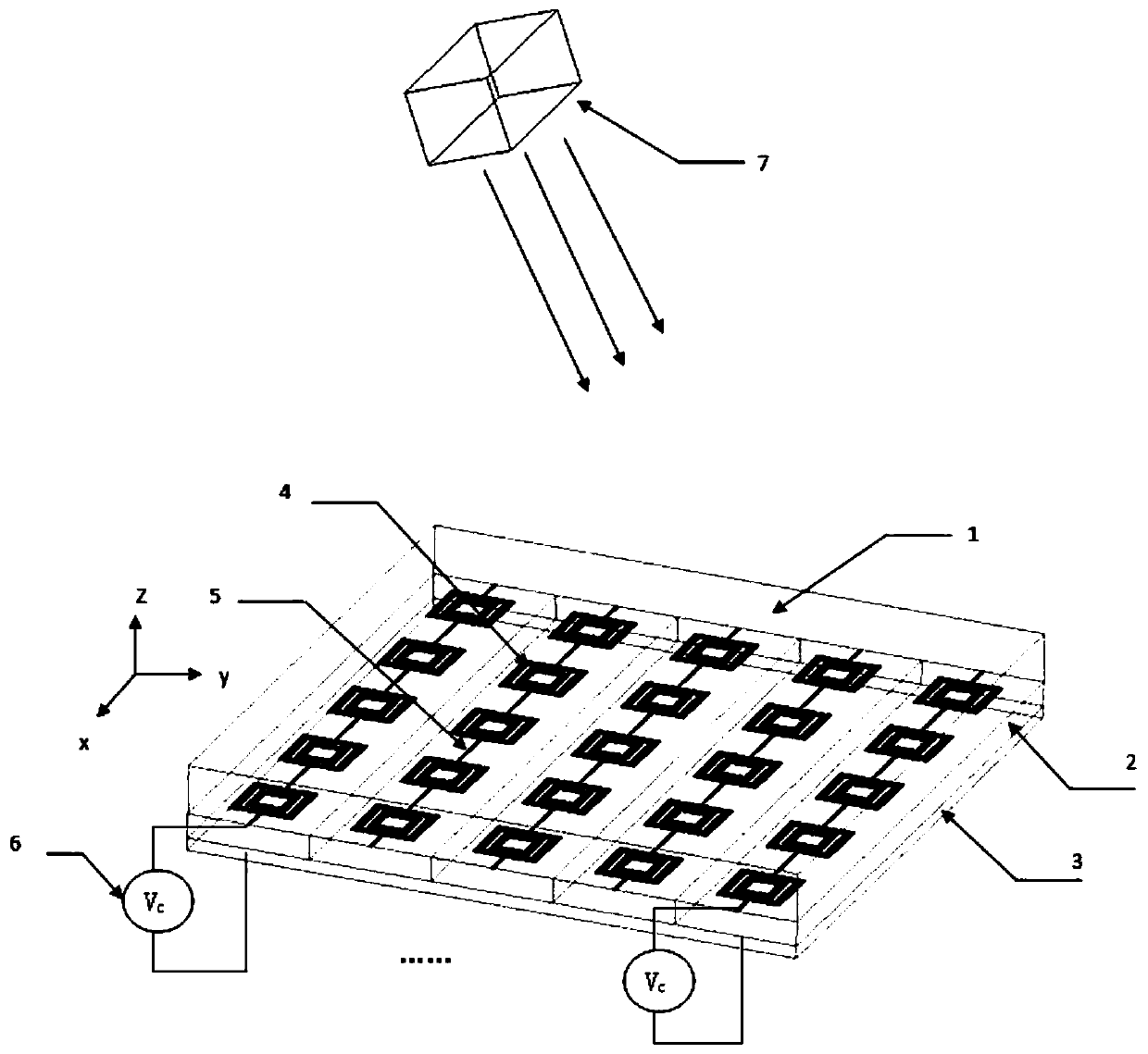
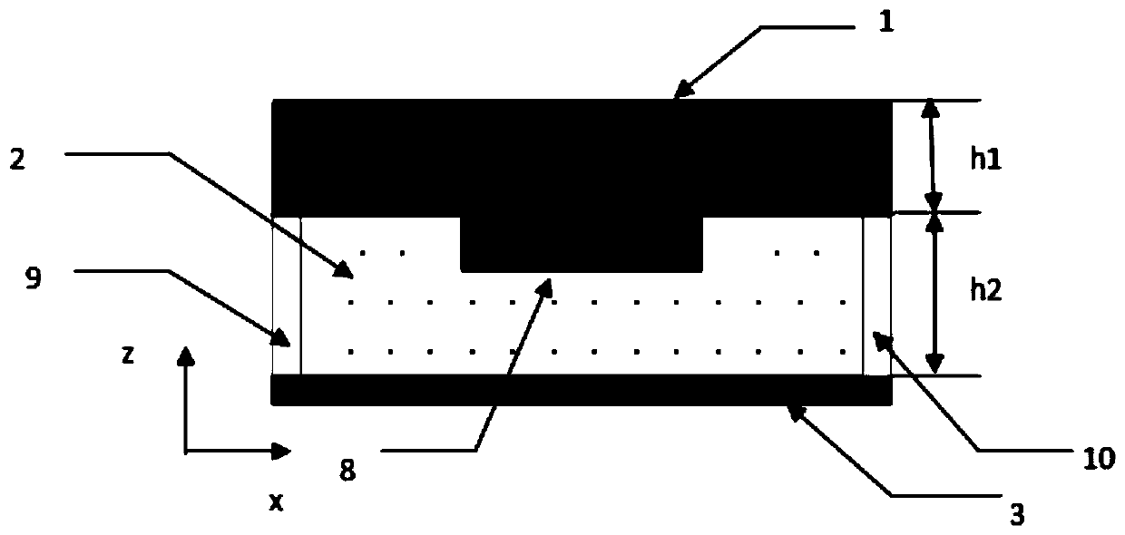
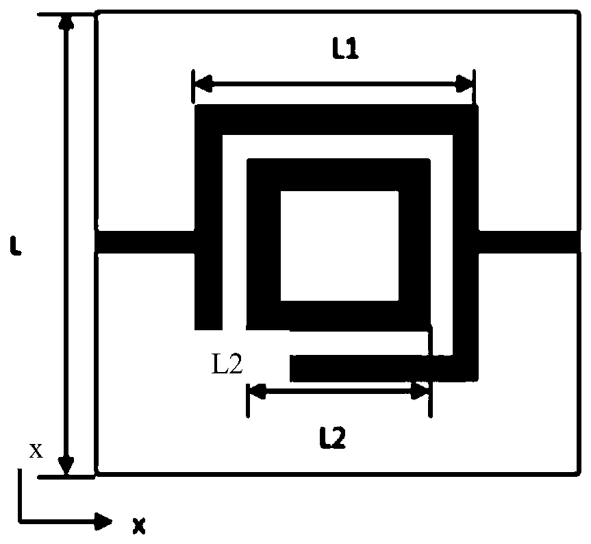
[0028] refer to figure 1 , the millimeter-wave reconfigurable antenna of the present invention includes a feed horn 7, a first dielectric layer 1 from top to bottom, a radiation array reflection surface layer 4 on the lower surface of the first dielectric layer, and is arranged under the radiation array reflection surface layer 4 The second dielectric layer 2 on the surface, and the grounding plate 3 arranged on the lower surface of the second dielectric layer. The radiation array reflection surface layer 4 is formed by periodic arrangement of M×N radiation units, and the values ​​of M and N are determined by antenna radiation efficiency, antenna gain, and the form of loading different antenna radiation units. In this embodiment, M=N=5, the unit radiator adopts a two-sided ring structure, and the radiating units in each column are connected by a bias line 5, and a DC bias voltage 6 is applied between the bias line 5 and the grounded metal plate, An electric field is formed be...


PUM


Abstract

The invention discloses a millimeter wave reconfigurable antenna, which belongs to the technical field of antennas. It includes a feed horn, a first dielectric layer, a radiation array reflective surface layer, a second dielectric layer, a ground plane, and a DC bias voltage connected between the radiation array reflective surface layer and the ground plane arranged in sequence from top to bottom. The present invention utilizes the characteristics that liquid crystal materials can exhibit different equivalent dielectric constant values ​​under different voltage controls, and by controlling the voltage loaded on each unit, the outgoing phase of the beam irradiated on the antenna unit can be changed, thereby realizing the antenna A change in the outgoing beam pattern. This method of controlling the outgoing direction of the beam through voltage has the advantages of simple structure, fast adjustment speed, and wide scanning angle range.

Description

technical field [0001] The invention belongs to the technical field of antennas, and in particular relates to a millimeter-wave reconfigurable antenna, which is widely used in fields such as wireless communication systems, satellite communication systems, and radar systems. Background technique [0002] As a component used to transmit or receive wireless electromagnetic waves, the antenna plays a vital role in wireless communication systems. In recent years, with the rapid development of the field of wireless communication, requirements for multi-frequency and multi-mode operation have been put forward for the antenna. In order to meet these requirements, people usually apply multiple antennas in the same system. This will not only increase the weight of the system, but also cause mutual interference between the antennas, thereby seriously affecting the normal operation of the antennas. In order to reduce electromagnetic interference, isolation devices can be added between...

Claims


Application Information

Patent Timeline
Patent Type & Authority Patents(China)
IPC IPC(8): H01Q3/36H01Q13/02H01Q15/14
CPCH01Q3/36H01Q13/02H01Q15/148
Inventor 李浩颜皋朋吴泽威李天明
Owner UNIV OF ELECTRONICS SCI & TECH OF CHINA
Why Eureka
Try Eureka