Gas Turbine Efficiency and Turndown Speed ​​Improvements Using Supplemental Air Systems

A technology for cooling air and fuel, which is applied in the direction of gas turbine devices, charging systems, turbine/propulsion fuel delivery systems, etc., which can solve problems such as availability fluctuations, and achieve the effect of improving efficiency and output

Active Publication Date: 2021-03-12
POWERPHASE
View PDF10 Cites 0 Cited by
  • Summary
  • Abstract
  • Description
  • Claims
  • Application Information

AI Technical Summary

Problems solved by technology

This is a growing challenge as renewable energy is becoming a larger part of the contemporary era and its availability fluctuates

Method used


Image

  • Gas Turbine Efficiency and Turndown Speed ​​Improvements Using Supplemental Air Systems
  • Gas Turbine Efficiency and Turndown Speed ​​Improvements Using Supplemental Air Systems
  • Gas Turbine Efficiency and Turndown Speed ​​Improvements Using Supplemental Air Systems

Examples


Embodiment Construction

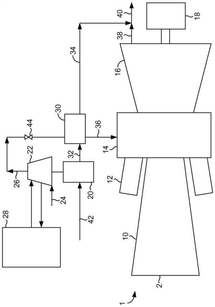
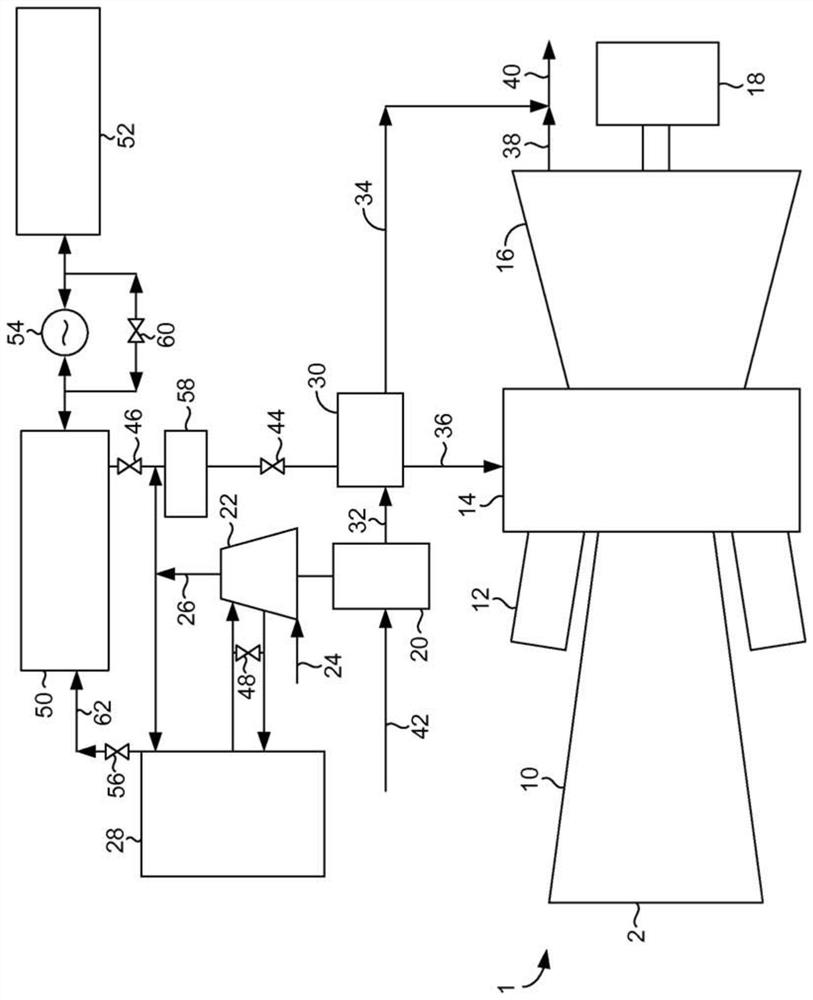
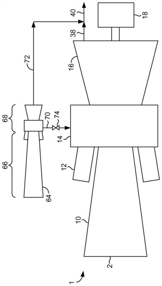
[0060] The components of one embodiment of the invention are in figure 1 are shown for their use with an existing gas turbine system 1 . A conventional gas turbine system 1 for compressing ambient air 2 includes a compressor 10 , a combustor 12 , a combustion box 14 , a turbine 16 and a generator 18 . The fuel engine 20 is used to drive a multi-stage intercooled supplemental compressor 22 which compresses ambient air 24 and discharges compressed air 26 . As used herein, the term "fuel engine" refers to a reciprocating internal combustion engine, a gas turbine (other than an oil-fired turbine in existing gas turbine systems 1 ), or a combustion engine such as gasoline, diesel, natural gas, or biofuels and similar fuels. A similar machine that converts fuel into energy through an exothermic reaction. The fuel engine draws in ambient air 42 and, as a result of the combustion process, produces hot exhaust gases 32 . As will be readily understood by those skilled in the art, as...


PUM


Abstract

The present invention discloses a novel apparatus and method for increasing the power of a gas turbine engine, improving gas turbine engine operation, and reducing the response time required to meet changing demands of a power plant. Power increases and engine operation improvements include additional heated compressed air injection, steam injection, water recovery, exhaust flashback, fuel heating and stored heated air injection.

Description

[0001] Cross References to Related Applications [0002] This application claims priority from a continuation-in-part of U.S. Patent Application Serial No. 14 / 350469, which claims priority from PCT / US2013 / 034748, filed March 31, 2013, which claims priority from April 2, 2012 Priority to filed U.S. Provisional Patent Application Serial No. 61 / 686222. technical field [0003] The present invention relates generally to gas turbine engine power systems, including energy storage to supplement the generating capacity of such gas turbine engines, and to provide additional power during periods of peak electrical demand. More specifically, a series of improvements to supplemental power generation systems are identified. Background technique [0004] Currently, marginal or peak power is primarily generated by gas turbines, operating in simple cycle or combined cycle configurations. As a result of the load demand distribution, the gas turbine base system is cycled up during periods o...

Claims


Application Information

Patent Timeline
Patent Type & Authority Patents(China)
IPC IPC(8): F02C6/16F02C7/224
CPCF02C7/224F02C3/305F02C6/02F02C6/18F05D2260/85Y02E20/14Y02E20/16
Inventor R.J.克拉夫特S.奥尔巴赫P.A.索比斯基S.A.阿里亚斯-昆特罗
Owner POWERPHASE
Why Eureka
Try Eureka