High-voltage rapidly charged lithium ion battery and preparation method thereof

A lithium-ion battery, high-voltage technology, applied in the manufacture of electrolyte batteries, non-aqueous electrolyte batteries, secondary batteries, etc., can solve the problems of shortening battery charging time, achieve product quality that is difficult to control, internal resistance is small, and contributes to Effect of rate discharge performance

Active Publication Date: 2017-03-08
GREAT POWER BATTRY ZHUHAI
View PDF3 Cites 5 Cited by
  • Summary
  • Abstract
  • Description
  • Claims
  • Application Information

AI Technical Summary

Problems solved by technology

With the acceleration of the pace of life and the development of electronic products, people hope that lithium-ion batteries have good fast charging capabilities to shorten the battery charging time; correspondingly, higher requirements are placed on the charging speed and voltage of lithium-ion batteries, but Due to the limitation of chemical materials, the current maximum operating voltage platform of a single cell is about 3.7V, and in order to meet the requirements of fast charging, lithium titanate is used as the negative electrode, and the operating voltage platform of a single cell is only 2.3-2.4V

Method used


Image

  • High-voltage rapidly charged lithium ion battery and preparation method thereof
  • High-voltage rapidly charged lithium ion battery and preparation method thereof
  • High-voltage rapidly charged lithium ion battery and preparation method thereof

Examples


Embodiment 1

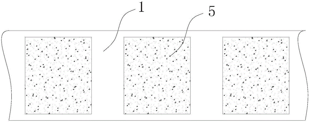
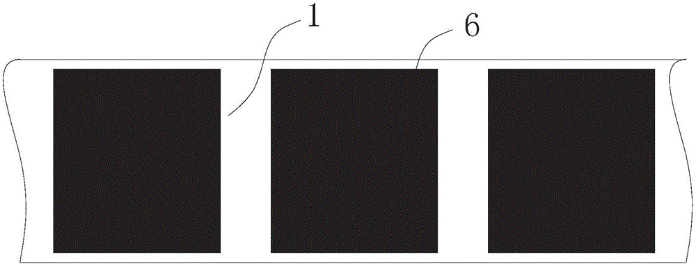
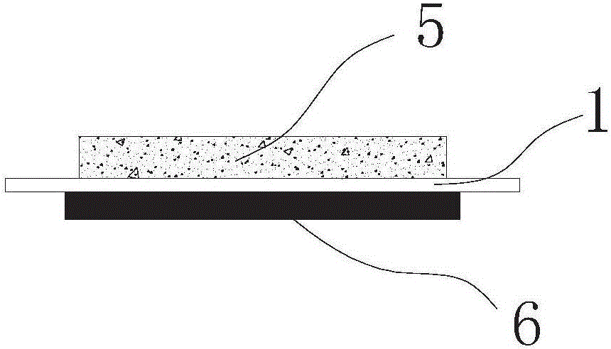
[0058] A high-voltage fast-charge lithium-ion battery, such as Figure 1 to Figure 15 As shown, it includes a separator 1, a pole piece, an electrolyte, a positive electrode collector 2, a negative electrode collector 3 and an aluminum-plastic film 4. Coating the positive electrode material to form the positive electrode 5 and coating the negative electrode material to form the negative electrode 6 are then die-cut and cut. The negative electrode material dressing area corresponding to the negative electrode 6 on the separator 1 covers the positive electrode material dressing area corresponding to the positive electrode 5. The die-cut diaphragm covers The dressing area corresponding to the positive electrode 5 and the negative electrode 6 respectively.

[0059] like Figure 4 As shown, two sheet-shaped separators (1a, 1b) with positive and negative electrodes after thermal die-cutting are arranged side by side and the polar materials on the same side of the separator are arra...

Embodiment 2

[0075] The structure of this embodiment is the same as that of Embodiment 1, and will not be repeated here; the difference is that the materials selected in this embodiment are different from those of Embodiment 1, as follows:

[0076] Step 1, select a diaphragm made of PP material as the coating substrate;

[0077] Step 2, using the intermittent coating method, at the positive corresponding positions on both sides of the diaphragm substrate, one side of the diaphragm substrate is coated with the lithium manganate material corresponding to the positive electrode, and the other side of the diaphragm substrate is coated with the corresponding negative electrode. The lithium titanate material, wherein, the lithium titanate material dressing area corresponding to the negative electrode covers the lithium manganate material dressing area corresponding to the positive electrode, and the separator covers the dressing areas corresponding to the negative electrode and the positive elect...

Embodiment 3

[0088] The structure of this embodiment is the same as that of Embodiment 1, and will not be repeated here; the difference is that the materials selected in this embodiment are different from those of Embodiment 1, as follows:

[0089] Step 1, select a diaphragm made of a combination of PE and double-sided ceramics as the coated substrate;

[0090] Step 2, using the intermittent coating method, at the corresponding positions on both sides of the diaphragm substrate, one side of the diaphragm substrate is coated with the nickel cobalt lithium manganese oxide material corresponding to the positive electrode, and the other side of the diaphragm substrate is single-coated The lithium titanate material corresponding to the negative electrode, wherein the lithium titanate material dressing area corresponding to the negative electrode covers the nickel cobalt lithium manganate material dressing area corresponding to the positive electrode, and the separator covers the dressing areas c...


PUM


Abstract

The invention provides a high-voltage rapidly charged lithium ion battery and a preparation method thereof. The high-voltage rapidly charged lithium ion battery comprises diaphragms, pole pieces, electrolyte, a cathode current collector, an anode current collector and an aluminum-plastic film, wherein each pole piece is prepared by taking the corresponding diaphragm gas a matrix, respectively coating two side surfaces of the matrix with a cathode material and an anode material intermittently to form a cathode and an anode and then carrying out die cutting and cropping; the two diaphragm pole pieces are arrayed side by side and are connected with each other in an insulation manner; the cathode current collector and the anode current collector which are distributed side by side are connected in an insulated manner, and then non-corroded surfaces of the cathode current collector and the anode current collector are fixedly adhered to one side of the inner layer of the aluminum-plastic film; and a series current collector through which a cathode and an anode of the other side of two sheet diaphragms which are connected in an insulated manner is fixedly adhered to the other side of the inner layer of the aluminum-plastic film. The invention further provides the preparation method of the high-voltage rapidly charged lithium ion battery. During processing, the diaphragms which are coated with the cathode material and the anode material are subjected to hot cutting, special foils are not required, after the surface of a foil of an existing current collector is subjected to corrosion treatment, a conductive material coats the surface of the foil, and then the foil is assembled to obtain the final product. The high-voltage rapidly charged lithium ion battery is simple and speedy, and meanwhile, the yield is high.

Description

[0001] 【Technical field】 [0002] The invention relates to lithium-ion battery manufacturing technology, in particular to a high-voltage fast-charge lithium-ion battery and a preparation method thereof. [0003] 【Background technique】 [0004] At present, lithium-ion batteries have the characteristics of high energy density, small self-discharge, wide operating temperature range, high voltage platform, long cycle life, no memory effect, and environmental friendliness, and have been widely used in mobile phones, notebook computers, power tools, etc. field. With the acceleration of the pace of life and the development of electronic products, people hope that lithium-ion batteries have good fast charging capabilities to shorten the battery charging time; correspondingly, higher requirements are placed on the charging speed and voltage of lithium-ion batteries, but Due to the limitation of chemical materials, the current maximum operating voltage platform of a single cell is about...

Claims


Application Information

Patent Timeline
Patent Type & Authority Applications(China)
IPC IPC(8): H01M2/14H01M4/485H01M4/66H01M10/0525H01M10/058H01M50/406
CPCH01M4/485H01M4/667H01M10/0525H01M10/058H01M50/403Y02E60/10Y02P70/50
Inventor 毛继勇许汉良张帆
Owner GREAT POWER BATTRY ZHUHAI
Why Eureka
Try Eureka