
Matrix power amplifier based on transistor stacking structure

A technology of power amplifier and stack structure, which is applied in power amplifiers, amplifiers with semiconductor devices/discharge tubes, amplifiers, etc., and can solve the problem of limited ultra-wideband high-power amplification capabilities, limited high-power and high-efficiency amplification capabilities, and increased Gate-source capacitance and other issues, achieve good broadband power output capability and power gain capability, avoid low breakdown voltage characteristics, and improve stability and reliability

Pending Publication Date: 2017-03-08
CHENGDU GANIDE TECH
View PDF7 Cites 12 Cited by
  • Summary
  • Abstract
  • Description
  • Claims
  • Application Information

AI Technical Summary

Problems solved by technology

[0004] (1) High-power and high-efficiency amplification capability is limited: With the development of semiconductor technology and the trend of proportional reduction in transistor size, the gate length of transistors is getting shorter and shorter, resulting in a decrease in breakdown voltage and an increase in knee voltage , thus limiting the transistor drain output voltage swing, which in turn limits the power capability of a single transistor
At present, a typical solution is to arrange multiple transistors (8 to 32) in parallel for power synthesis to improve power tolerance. However, this solution increases gate-source capacitance, reduces input impedance, and increases It eliminates the difficulty of designing the impedance matching of the input circuit. At the same time, the optimal output load impedance of the transistor amplifier using this structure is very small, and an additional output impedance matching network is required for the impedance matching design of the output circuit. Therefore, the output is also increased. The impedance matching design of the circuit is difficult. At the same time, using multiple transistors arranged in parallel to form a composite structure will occupy a large chip area, thereby greatly increasing the chip production cost.
[0005] (2) Ultra-wideband high power amplification capability is limited: In the design process of RF power amplifiers, affected by the gain-bandwidth product of transistors, designers always have to compromise between the two indicators of power amplifier bandwidth and power gain
[0007] It can be seen that the design difficulties of ultra-wideband RF power amplifiers based on integrated circuit technology are: (1) high power output under ultra-wideband is more difficult; (2) high power gain under ultra-wideband is more difficult; (3) ) The chip area of ​​the traditional method under UWB is relatively large

Method used


Image

  • Matrix power amplifier based on transistor stacking structure
  • Matrix power amplifier based on transistor stacking structure
  • Matrix power amplifier based on transistor stacking structure

Examples


Embodiment Construction

[0031] The principles and features of the present invention are described below in conjunction with the accompanying drawings, and the examples given are only used to explain the present invention, and are not intended to limit the scope of the present invention.

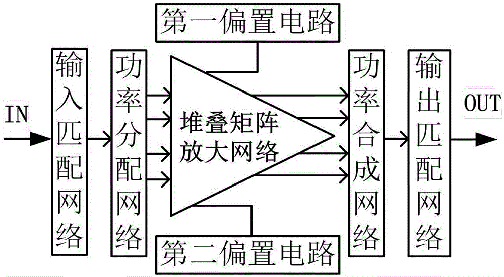
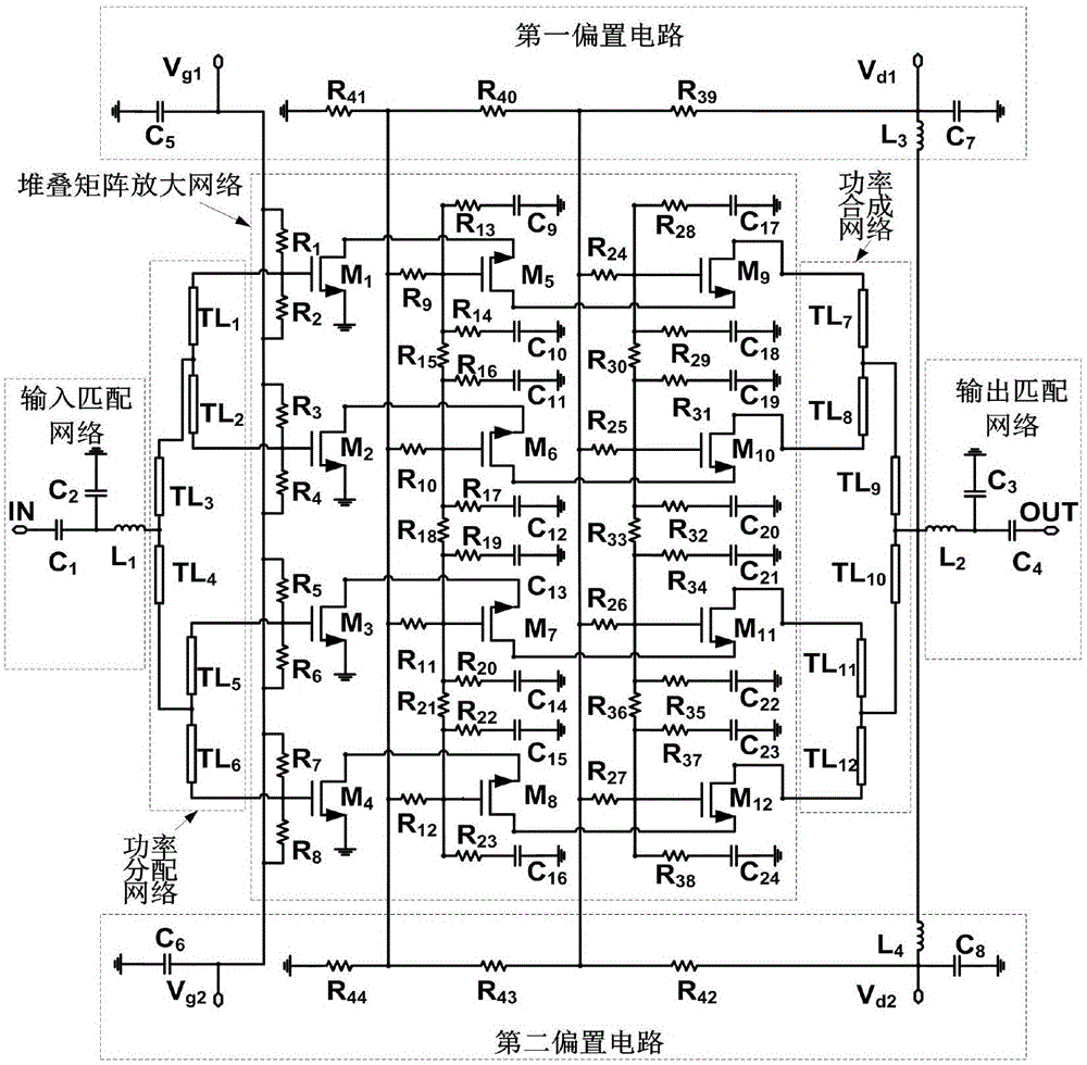
[0032] Such as figure 1 , figure 2 As shown, a matrix power amplifier based on a transistor stack structure provided by the present invention is an ultra-wideband radio frequency power amplifier using a transistor stack matrix amplification network structure, which is designed using an integrated circuit process, including sequentially connected input matching networks, A power distribution network, a stacked matrix amplifying network, a power combining network and an output matching network, and a first bias circuit and a second biasing circuit respectively symmetrically connected to the stacked matrix amplifying network, wherein the stacking matrix amplifying network is an active amplifying network , the input m...


PUM


Abstract

The invention discloses a matrix power amplifier based on a transistor stacking structure. The matrix power amplifier comprises an input matching network, a power distribution network, a stacked matrix amplification network, a power synthetic network and an output matching network, which are connected in sequence, and a first biasing circuit and a second biasing circuit which are symmetrically connected with the stacked matrix amplification network respectively. A power amplifier chip circuit realized by the matrix power amplifier based on the transistor stacking structure is wide in bandwidth, high in output power, high in power gains and small in area.

Description

technical field [0001] The invention relates to field effect transistor radio frequency power amplifiers and the field of integrated circuits, in particular to a matrix power amplifier based on a transistor stacking structure applied to a transmitting module at the end of an ultra-wideband transceiver. Background technique [0002] With the rapid development of wireless communication markets such as ultra-wideband communication, software radio, and wireless local area network (WLAN), RF front-end transceivers are also required to develop in the direction of high integration, low power consumption, compact structure, and low price. [0003] As an important module of the transmitter, the RF and microwave power amplifier is the circuit that consumes the most energy in the entire transmitter, and its output power requirements are relatively high. When the integrated circuit process is used to design and implement the chip circuit of the RF and microwave power amplifier, its perfo...

Claims


Application Information

Patent Timeline
IPC IPC(8): H03F1/56H03F3/193H03F3/21
CPCH03F1/565H03F3/193H03F3/21H03F2200/451
Inventor 胡柳林邬海峰滑育楠陈依军廖学介吕继平童伟王测天
Owner CHENGDU GANIDE TECH
Learn More