Hydrogen-energy mixed gas production equipment and method

A technology for mixing gas and production equipment, applied in the direction of fuel, gas fuel, climate sustainability, etc., can solve the problems of reduced hydrogen and oxygen electrolysis efficiency, poor stability, large calorific value, etc., to improve heat transfer efficiency, control Convenience and the effect of reducing power consumption

Inactive Publication Date: 2018-09-25
山东格瑞斯新能源科技有限公司
View PDF9 Cites 0 Cited by
  • Summary
  • Abstract
  • Description
  • Claims
  • Application Information

AI Technical Summary

Problems solved by technology

Hydrogen energy is the most environmentally friendly renewable energy in the new century. However, due to the many unsolvable problems in the preparation, storage, transportation and safety application of hydrogen energy, it is difficult to be widely used in civilian industries. The oxygen generator includes an electrolytic cell, a gas outlet on the upper end of the electrolytic cell, and positive and negative electrodes inside the electrolytic cell. However, due to the high calorific value of the positive and negative conductive electrodes, the gas temperature is high when generating hydrogen and oxygen, and the atoms are more stable. Active and poor stability, the bubbles on the electrode plate are easy to accumulate and prevent the current from passing. At this time, hydrogen atoms and oxygen atoms are easy to recombine to form water molecules, resulting in a decrease in the efficiency of electrolysis of hydrogen and oxygen, and relatively high energy consumption.

Method used


Image

  • Hydrogen-energy mixed gas production equipment and method
  • Hydrogen-energy mixed gas production equipment and method
  • Hydrogen-energy mixed gas production equipment and method

Examples


Embodiment 1

[0029] Assembly of hydrogen energy mixed gas production equipment:

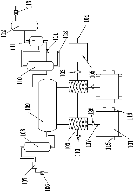
[0030] The hydrogen energy mixed gas production equipment includes an electrolyzer 101, a heat exchanger 103, a primary gas-liquid separation device 109, a catalyst catalytic mixing device 110, a secondary gas-liquid separation device 111, and a gas buffer tank 112. The primary gas The water inlet of the liquid separation device 109 communicates with the water level adjustment water tank 108 through a pipeline, and the water level adjustment controller 106 and the water level adjustment pump 107 are installed on the water inlet pipeline of the water level adjustment water tank 108; The pipeline is communicated with a heat exchanger 103, and the air inlet of the heat exchanger 103 is communicated with the hydrogen-oxygen mixed gas outlet 117 of an electrolytic cell 101 through a pipeline, and an electrolyte circulation is installed on the pipeline that the heat exchanger 103 communicates with the electrolytic c...

Embodiment 2

[0038] Assembly of hydrogen energy mixed gas production equipment:

[0039] The hydrogen energy mixed gas production equipment includes an electrolyzer 101, a heat exchanger 103, a primary gas-liquid separation device 109, a catalyst catalytic mixing device 110, a secondary gas-liquid separation device 111, and a gas buffer tank 112. The primary gas The water inlet of the liquid separation device 109 communicates with the water level adjustment water tank 108 through a pipeline, and the water level adjustment controller 106 and the water level adjustment pump 107 are installed on the water inlet pipeline of the water level adjustment water tank 108; The pipeline is communicated with two heat exchangers 103, and the cooling water outlet and the cooling water inlet between the two heat exchangers 103 are communicated by pipelines, and the air inlet of each heat exchanger 103 is connected with the oxygen hydrogen of an electrolyzer 101 by pipelines. The mixed gas outlet 117 commu...

Embodiment 3

[0047] Assembly of hydrogen energy mixed gas production equipment:

[0048] The hydrogen energy mixed gas production equipment includes an electrolyzer 101, a heat exchanger 103, a primary gas-liquid separation device 109, a catalyst catalytic mixing device 110, a secondary gas-liquid separation device 111, and a gas buffer tank 112. The primary gas The water inlet of the liquid separation device 109 communicates with the water level adjustment water tank 108 through a pipeline, and the water level adjustment controller 106 and the water level adjustment pump 107 are installed on the water inlet pipeline of the water level adjustment water tank 108; The pipeline is communicated with three heat exchangers 103, and the cooling water outlet and the cooling water inlet between the three heat exchangers 103 are communicated by pipelines, and the air inlet of each heat exchanger 103 is connected with the oxygen hydrogen of an electrolyzer 101 by pipelines. The mixed gas outlet 117 c...


PUM


Abstract

The invention discloses a hydrogen energy mixed gas production device and method. The device structurally comprises electrolytic baths, a first-stage gas-liquid separation device, an accelerant catalyzing and mixing device, a second-stage gas-liquid separation device and a gas buffer tank. A water inlet of the first-stage gas-liquid separation device communicates with a water level adjusting water tank through a pipeline, and a gas inlet of the first-stage gas-liquid separation device communicates with each of heat exchangers through a pipeline. A gas inlet of each heat exchanger communicates with the corresponding electrolytic bath through a pipeline. An outlet of the first-stage gas-liquid separation device communicates with the accelerant catalyzing and mixing device through a pipeline. A top outlet of the accelerant catalyzing and mixing device communicates with the second-stage gas-liquid separation device through a pipeline. A top gas outlet of the second-stage gas-liquid separation device communicates with the gas buffer tank through a pipeline. A gas outlet of the gas buffer tank communicates with an industrial gas boiler through a gas pipeline. According to the hydrogen energy mixed gas production device and method, electric energy consumption is reduced, the heat transfer efficiency in the whole gas making process is improved, generated hydrogen energy mixed gas is immediately used while being produced, and the danger of gas storage leakage is avoided.

Description

technical field [0001] The invention relates to the technical field of new energy combustion, in particular to a hydrogen energy mixed gas production equipment and method. Background technique [0002] With the development of the national economy, the country's annual fuel consumption has exceeded 450 million tons. Huge fuel consumption not only puts huge pressure on the increasingly depleted petroleum energy, but also a large amount of floating carbon, hydrocarbons (HC), carbon monoxide (CO) and nitrogen oxides (NO) emitted from improper combustion of fuel oil X ), sulfur dioxide (SO 2 ) has become the main source of pollutants in large and medium-sized cities. In recent years, due to the smog and haze produced by the combustion of fossil fuels, air pollution has greatly damaged the ecological environment of the earth and seriously affected people's health. Because of the urgent requirements of energy saving and environmental protection, major countries in the world are ...

Claims


Application Information

Patent Timeline
Patent Type & Authority Patents(China)
IPC IPC(8): C25B1/04C25B15/08C10L3/00
CPCC10L3/00C10L2290/141C25B1/04C25B15/08Y02E60/36Y02P20/10
Inventor 徐立根何坚聂军玲
Owner 山东格瑞斯新能源科技有限公司
Why Eureka
Try Eureka