
Pulsed power supply for electric spark machine tool

A technology for processing machine tools and pulse power supplies, which is applied in electric processing equipment, metal processing equipment, circuits, etc., and can solve problems such as affecting processing efficiency and processing quality, and inconvenient operation.

Active Publication Date: 2017-04-19
保时杰数控机床江苏有限公司
View PDF8 Cites 4 Cited by
  • Summary
  • Abstract
  • Description
  • Claims
  • Application Information

AI Technical Summary

Problems solved by technology

[0002] The output voltage of the pulse power supply used in electric discharge machine tools such as wire cutting machine tools and punching machine tools is preset. There is no automatic voltage regulation function during the EDM process. The feed speed of the carriage is the feed of the workpiece. The speed should match the voltage of the pulse power supply. If the feed speed is too fast, the workpiece will contact with the electrode to form a short circuit. If the feed speed is too slow, an open circuit will be formed between the workpiece and the electrode. Both phenomena will affect the processing efficiency and Processing quality; in order to maintain a reasonable gap between the electrode and the workpiece to generate spark discharge, the operator needs to repeatedly adjust the feed parameters according to the processing situation, which brings great inconvenience to the operation

Method used


Image

  • Pulsed power supply for electric spark machine tool
  • Pulsed power supply for electric spark machine tool
  • Pulsed power supply for electric spark machine tool

Examples


no. 2 example

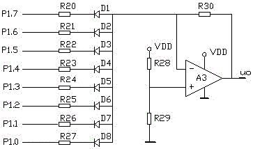
[0022] The second embodiment: the difference between the second embodiment and the first embodiment is that the D / A converter described in the second embodiment includes resistors R20-R30, diodes D1-D8, operational amplifier A3, and the P1 port Pin P1.7 is connected to the cathode of diode D1 through resistor R20, pin P1.6 of port P1 is connected to the cathode of diode D2 through resistor R21, pin P1.5 of port P1 is connected to the cathode of diode D3 through resistor R22, port P1 The pin P1.4 of the P1 port is connected to the cathode of the diode D4 through the resistor R23, the pin P1.3 of the P1 port is connected to the cathode of the diode D5 through the resistor R24, and the pin P1.2 of the P1 port is connected to the cathode of the diode D6 through the resistor R25, P1 The pin P1.1 of the port is connected to the cathode of the diode D7 through the resistor R26, the pin P1.0 of the P1 port is connected to the cathode of the diode D8 through the resistor R27, and the an...


PUM


Abstract

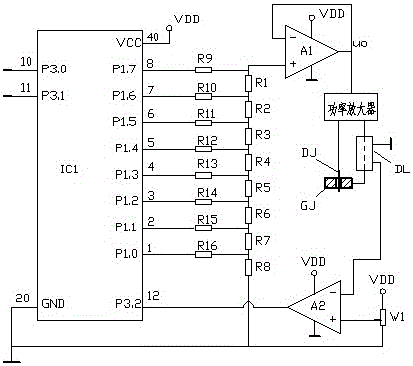
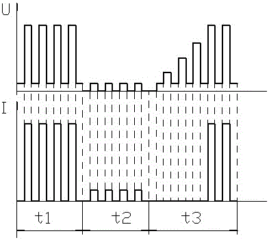
The invention relates to a pulsed power supply for an electric spark machine tool. The pulsed power supply for the electric spark machine tool comprises a pulse signal forming circuit, a power amplifier for carrying out power amplification on a pulse signal, and a current detecting circuit for detecting output current of the power amplifier. The pulse signal forming circuit comprises a single-chip microcomputer IC1 and a D / A (Digital-to-Analog) converter. The single-chip microcomputer is connected with an input port of the D / A converter; the output end of the D / A converter is connected with the input end of the power amplifier; an electrode DJ as a load and a workpiece GJ are connected into an output circuit of the power amplifier; a voltage value of a discharge pulse is automatically controlled through the single-chip microcomputer, so that the voltage of the discharge pulse outputted by a pulsed power supply is matched with the cutting speed, the normal spark discharge is maintained, the machining efficiency and the machining quality are improved, and meanwhile, the inconvenience caused by adjusting the cutting speed through manual work is avoided; and the current detecting circuit detects short-circuit current when a low-voltage detecting pulse occurs, so that a wire electrode can be prevented from being damaged, the occurrence of arc discharge can be prevented when the workpiece is deviated from an electrode, and the reduction of the finish degree of the workpiece is avoided.

Description

technical field [0001] The invention relates to a pulse power supply, which is used in an electric discharge machine tool as a discharge power supply. Background technique [0002] The output voltage of the pulse power supply used in electric discharge machine tools such as wire cutting machine tools and punching machine tools is preset. There is no automatic voltage regulation function during the EDM process. The feed speed of the carriage is the feed of the workpiece. The speed should match the voltage of the pulse power supply. If the feed speed is too fast, the workpiece will contact with the electrode to form a short circuit. If the feed speed is too slow, an open circuit will be formed between the workpiece and the electrode. Both phenomena will affect the processing efficiency and Processing quality; in order to maintain a reasonable gap between the electrode and the workpiece to generate spark discharge, the operator needs to repeatedly adjust the feed parameters acc...

Claims


Application Information

Patent Timeline
IPC IPC(8): B23H1/02
CPCB23H1/02
Inventor 丁毅
Owner 保时杰数控机床江苏有限公司
Learn More