

Gas-liquid separating drum for flue gas dewatering, dewatering device and system
A gas-liquid separation and dehydration device technology, applied in separation methods, dispersed particle separation, chemical instruments and methods, etc., can solve the problems of secondary entrainment, inability to achieve gas-liquid separation, etc., to achieve easy maintenance and improve equipment operation stability , the effect of improving efficiency
- Summary
- Abstract
- Description
- Claims
- Application Information
AI Technical Summary
Problems solved by technology
Method used
Image

Examples
Embodiment 1
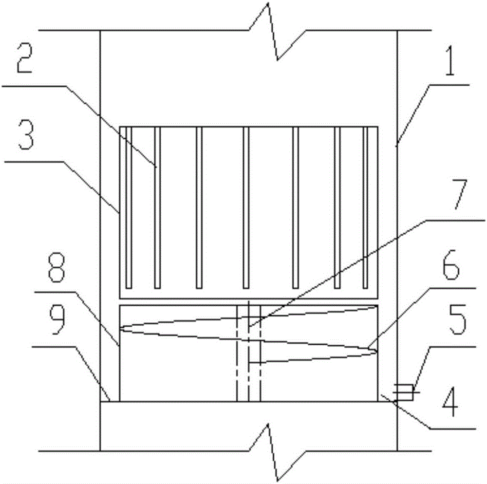
[0053] figure 1 Among them, the gas-liquid separation cylinder 3 includes a cylinder body, and a plurality of slits 2 are vertically (or inclined) on the cylinder body, and the width of the slits 2 is 2-10mm (preferably 6mm), and the spacing is the width 5-20 times (preferably 10 times) of that.
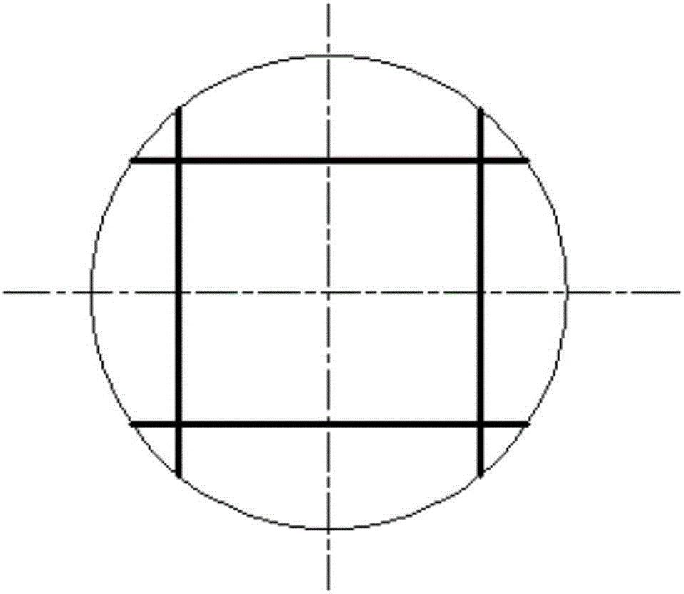
[0054] The slit wherein also can be changed into grid form, if adopt grid then grid height is 5-20cm (preferably 12cm), and gap is grid height 0.5-20 times (preferably 5 times).
[0055] Or, the slit is changed into a hole, and the shape of the hole can be a round hole, a square hole, an elliptical hole, a hexagonal hole, etc., no matter which type of hole, its radial maximum size is 2-10mm (preferably 6mm), the hole The pitch is 5-20 times (preferably 10 times) the largest dimension.
[0056] Through the design of the above form, after the moisture in the flue gas is thrown to the inner wall of the cylinder, it can be transferred from the inner wall of the cylinder to the outer wa...
Embodiment 2
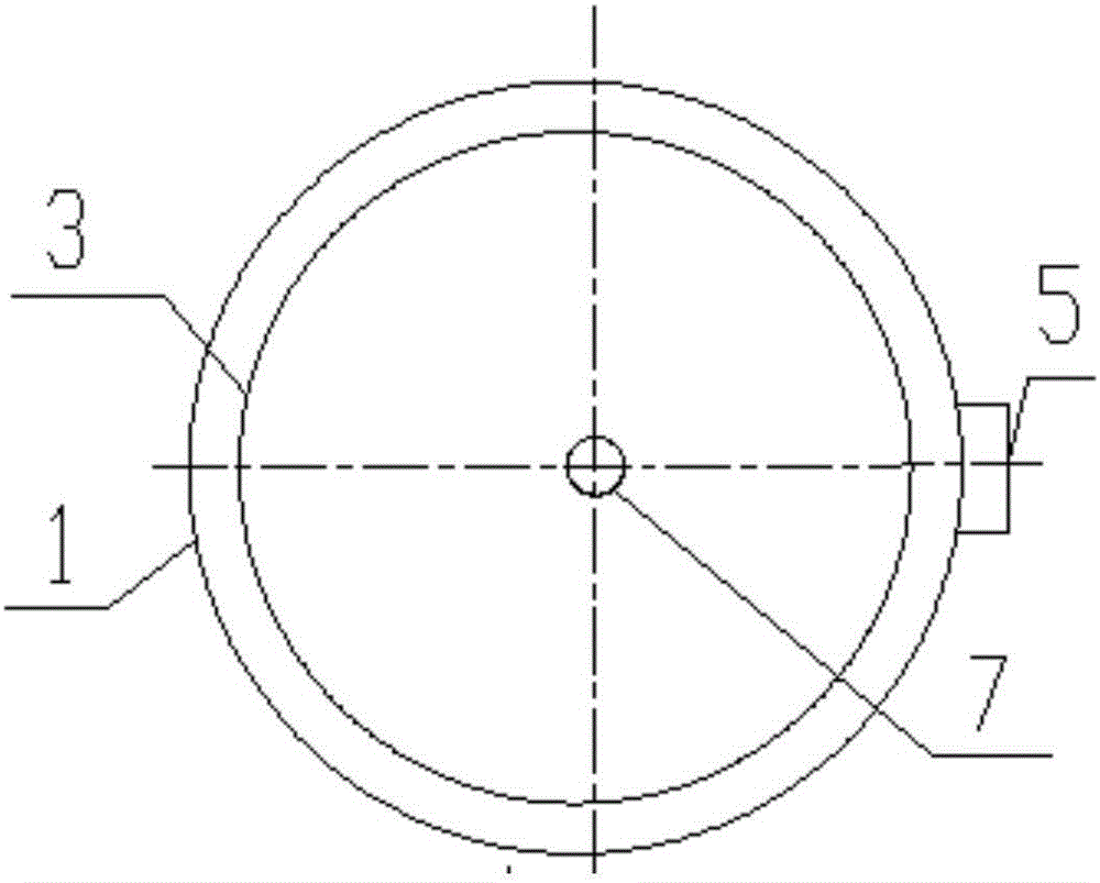
[0058] figure 1 , figure 2 In , a schematic diagram of the structure of a dehydration device is given, which is installed in the flue 1. Wherein, the lower part of the gas-liquid separation cylinder 3 is a flue gas guiding device, and the flue gas guiding device is composed of a flue gas channel 8 and blades therein. The blade can adopt the existing multi-blade form (no longer show the drawings), as far as the present invention is concerned, a structural schematic diagram of the helical fin 6 that is a single blade is provided. The helical tooth piece 6 of the flue gas guide device is a tooth piece that spirals up around the central axis 7. The total height of the helical tooth piece 6 is 200-600mm (preferably 450mm), and it rotates 360-540° (preferably 450mm) around the central axis 7. °), the diameter of the central axis 7 accounts for 10% to 30% (preferably 20%) of the outer diameter of the helical tooth piece 6. The flue gas is guided along the helical tooth piece 6, a...
Embodiment 3
[0061] Figure 1-3 Among them, the entire gas-liquid separation system also includes a liquid collection tank 4 and a water diversion port 5. The liquid collection tank 4 can be installed on the lower periphery of the gas-liquid separation cylinder 3, and can also be installed on the lower periphery of the flue gas channel 8, so that the The liquid flowing out along the gas-liquid separation cylinder 3 is collected, and at least one water introduction port 5 is provided at the lowest end of the liquid collection tank 4 to lead the collected liquid out of the flue 1 for subsequent further processing.
[0062] Similarly, the above gas-liquid separation system can not only separate gas-liquid, but also can be used in gas-oil separation. Due to the density difference between gas and oil, the oil has a high density and high inertia, and is captured by the separation barrel or grid sheet; while the gas flow Because of the low density and low inertia, the spiral rising process is alw...
PUM
| Property | Measurement | Unit |
|---|---|---|
| Size | aaaaa | aaaaa |
| Height | aaaaa | aaaaa |
Abstract
Description
Claims
Application Information