Diamond coating cutter and manufacturing method thereof

A cutting tool and diamond coating technology, which is applied to drilling tool accessories, tools for lathes, tools for milling machines, etc., can solve the problems of polluting the vacuum chamber, being unavailable, and destroying the quality and purity of the diamond film. The effect of reducing manufacturing costs and reducing production costs

Inactive Publication Date: 2017-04-26
天钻科技股份有限公司
View PDF7 Cites 5 Cited by
  • Summary
  • Abstract
  • Description
  • Claims
  • Application Information

AI Technical Summary

Problems solved by technology

[0015] The second point: Since the deposition reaction of the CVD diamond coating is carried out in a low-pressure vacuum chamber, the reaction pressure of the general CVD diamond coating is less than 50 Torr (torr), and the silver base of the welding place of the traditional welded tungsten carbide tool 300 Or in copper-based solder, the element zinc (Zn) with low melting point and high vapor pressure will volatilize in a large amount under the low-pressure environment of CVD diamond coating, pollute the entire vacuum chamber, interfere with the CVD reaction of diamond growth, and destroy the deposited diamond. Membrane Quality and Purity
[0016] Therefore, CVD diamond-coated welded tungsten carbide tools are still not available

Method used


Image

  • Diamond coating cutter and manufacturing method thereof
  • Diamond coating cutter and manufacturing method thereof
  • Diamond coating cutter and manufacturing method thereof

Examples


Embodiment Construction

[0050] The following is a detailed description according to the embodiment shown in the drawings:

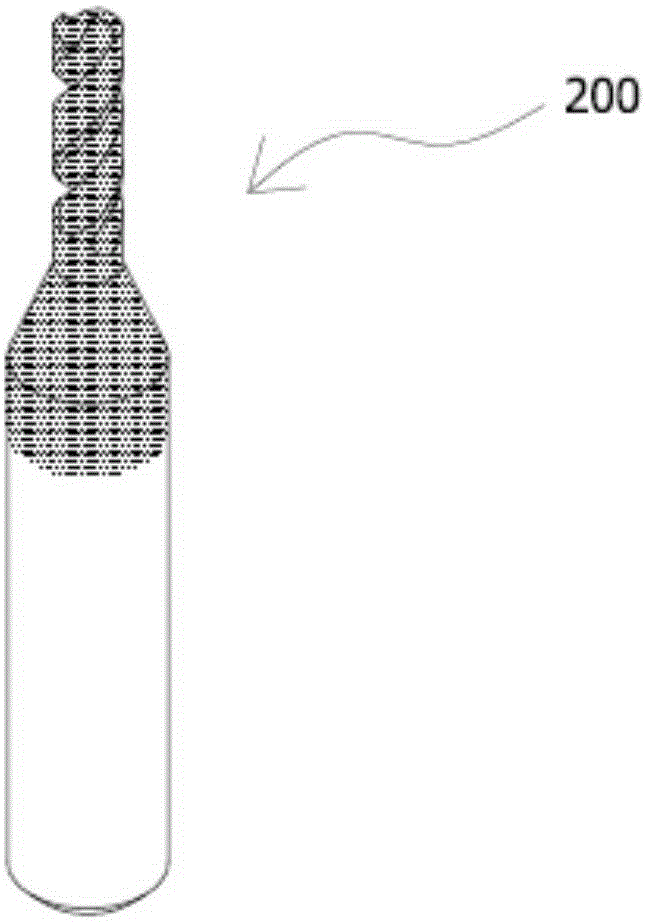
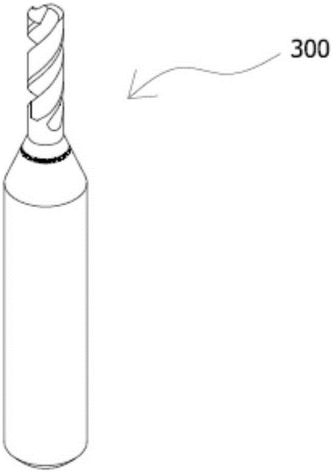
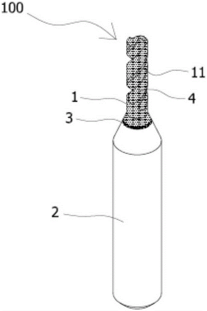
[0051] Such as image 3 , Figure 5 to Figure 7 As shown in the figure, a diamond-coated cutting tool is disclosed, which is characterized in that: the diamond-coated cutting tool 100 includes a first section of rod 1, which is cylindrical and made of sintered tungsten carbide material, and The outer surface is provided with at least one blade portion 11, which can be used for cutting; a second segment bar 2 is cylindrical and made of metal material, and the top is connected with the bottom end of the first segment bar 1, which can It is used for clamping the machine tool; a welding part 3, for the application of high-temperature solder S, is arranged between the bottom end of the first section bar 1 and the top end of the second section bar 2, and is used to join the first section bar 1 The second section of the rod 2 ; and a diamond film 4 are coated on the entire surface of...


PUM

PropertyMeasurementUnit
melting pointaaaaaaaaaa

Abstract

The invention aims at providing a diamond coating cutter and a manufacturing method thereof. The diamond coating cutter comprises a first section of cylindrical bar, a second section of cylindrical bar, a welding part and a diamond film. The first section of cylindrical bar is made of sintered tungsten carbide materials. The second section of cylindrical bar is made of metal materials. The welding part is located between the first section of bar and the second section of bar. The whole surface of the first section of bar is coated with the diamond film through a chemical vapor deposition manufacturing procedure. The manufacturing method of the diamond coating cutter comprises the steps that firstly, sintered tungsten carbide and the metal bar are combined into a bar material with high-temperature solder through a hard soldering manufacturing procedure in a butt joint mode; then after forming machining, the cutter with the first section of bar, the second section of bar and the welding part can be obtained preliminarily; and then the chemical vapor deposition manufacturing procedure is conducted on the cutter, so that the whole surface of the first section of bar is coated with the diamond film, and finally the diamond coating cutter is obtained.

Description

technical field [0001] The invention relates to a diamond-coated cutting tool and a manufacturing method thereof, in particular to a cutting tool used in mechanical processing of printed circuit boards (Printed Circuit Board, PCB) and a manufacturing method thereof. Background technique [0002] Rotary cutting tungsten carbide circular tools commonly used in the machining process of printed circuit boards include: printed circuit board drills (PCB drill) for mechanical drilling, and milling cutters for printed circuit board molding and appearance processing (router), end mill (end mill). [0003] The base material of the printed circuit board is mainly made of composite materials composed of resin, glass fiber and copper skin, so its cutting process has a certain degree of complexity; in terms of machinability, glass fiber is relatively hard, and it will cause damage to tungsten carbide tools. Larger wear, and the wear of resin on tungsten carbide tools is only about half o...

Claims


Application Information

Patent Timeline
Patent Type & Authority Applications(China)
IPC IPC(8): B23B51/02B23C5/02B23P15/32B23P15/34
CPCB23B51/02B23B2226/42B23C5/02B23C2226/42B23P15/32B23P15/34
Inventor 颜天渊
Owner 天钻科技股份有限公司
Why Eureka
Try Eureka