
Interdigital organic pollutant photodegradation device and preparation method thereof

A technology for organic pollutants and photodegradation, applied in water pollutants, chemical instruments and methods, chemical/physical processes, etc., can solve the problems of low catalytic efficiency, complex process, and high production costs, and achieve high surface activity and production. Simple method and low cost effect

Active Publication Date: 2017-04-26
XI AN JIAOTONG UNIV
View PDF7 Cites 1 Cited by
  • Summary
  • Abstract
  • Description
  • Claims
  • Application Information

AI Technical Summary

Problems solved by technology

In the past, photocatalytic reactors were mostly planar structures, and their catalytic efficiency was low; in addition, curved surface reactors based on microchannels needed to be prepared by microfabrication techniques such as exposure and etching, and the process was complicated and the production cost was high.

Method used


Image

  • Interdigital organic pollutant photodegradation device and preparation method thereof
  • Interdigital organic pollutant photodegradation device and preparation method thereof
  • Interdigital organic pollutant photodegradation device and preparation method thereof

Examples


preparation example Construction

[0031] The preparation method of the present invention is as follows:

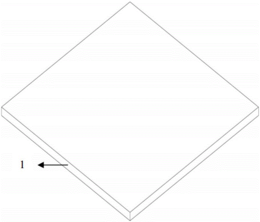
[0032] 1) see figure 1 , ultrasonically clean glass with a length and width of 34mm×34mm~35mm×35mm with acetone, absolute ethanol and deionized water, and dry at room temperature;

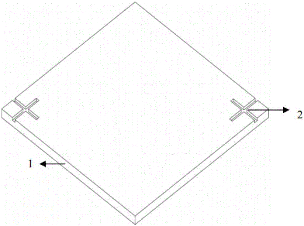
[0033] 2) see figure 2 , using a laser marking machine to make cross-shaped alignment marks on the upper right corner and lower left corner of one glass substrate respectively, and set cross-shaped alignment marks on the upper left corner and lower right corner of the second glass substrate, the length and width of the engraved lines are respectively 4-5mm, 1-2mm, and the horizontal and vertical distances of the two cross-shaped alignment marks are both 24-25mm, ultrasonic cleaning with absolute ethanol and deionized water in turn, and drying at room temperature;

[0034] 3) Take several sections of optical fiber with a length of 2 to 3 cm, immerse them in acetone, pull out the fiber core from the cladding, ultrasonically cl...

specific Embodiment

[0043] The preparation method of the present invention comprises the following steps:

[0044] 1) Ultrasonic cleaning of glass with a length, width and thickness of 34mm×34mm×1mm with acetone, absolute ethanol and deionized water, and drying at room temperature, as figure 1 shown;

[0045] 2) Use a laser marking machine to make cross-shaped alignment marks on the upper right corner and lower left corner of the glass substrate respectively. 24mm, followed by ultrasonic cleaning with absolute ethanol and deionized water for 5 minutes, and dried at room temperature, such as figure 2 shown;

[0046] 3) Take several sections of optical fiber with a length of 2 cm, and immerse them in acetone for 10 minutes, pull out the fiber core from the cladding, ultrasonically clean them with absolute ethanol and deionized water for 5 minutes, and dry them at room temperature;

[0047] 4) Prepare PDMS glue with PDMSA:PDMSB at a mass ratio of 10:1;

[0048] 5) On the first glass substrate, ...


PUM

PropertyMeasurementUnit
diameteraaaaaaaaaa
lengthaaaaaaaaaa
diameteraaaaaaaaaa

Abstract

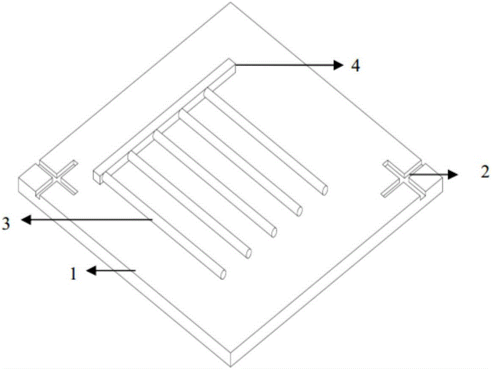
The invention discloses an interdigital organic pollutant photodegradation device and a preparation method thereof, optical fiber cores are arranged and fixed on a glass substrate for forming a three-dimensional cylindrical micron structure, ZnO nanowires are synthesized on the three-dimensional cylindrical micron grid line structure, the response area in the same projection area of an obtained three-dimensional cylindrical multi-scale structure array is larger than that of a plane structure, the miniaturization of a micro channel can be achieved; the ZnO nanowires synthesized on the three-dimensional cylindrical micron grid line structure have good divergence can increase the light catalytic effective area, at the same time, the surface activity of the ZnO nanowires is high, electron hole pairs are easy to produce, improvement of the light degradation efficiency is facilitated.

Description

technical field [0001] The invention belongs to the technical field of micro-nano manufacturing, and in particular relates to an interdigitated organic pollutant photodegrader and a preparation method thereof. Background technique [0002] Photocatalytic degradation mainly uses semiconductor materials as catalysts, which can effectively use solar energy to photocatalytically degrade toxic pollutants, and has the characteristics of high efficiency, environmental protection, and energy saving. With the continuous development of microfabrication technology, microchannels have received extensive attention in the field of sewage treatment, especially microchannels modified by nanomaterials. For example: Zhitao Han et al. prepared a microchannel with a rectangular structure on a silicon wafer by photolithography, and synthesized ZnO nanowires on the inner wall of the microchannel by a water bath method. High degradation efficiency. Zhaoxu Meng et al. used soft lithography to pre...

Claims


Application Information

Patent Timeline
Patent Type & Authority Applications(China)
IPC IPC(8): C02F1/30B01J23/06C02F101/30
CPCC02F1/30B01J23/06C02F2305/10C02F2101/30B01J35/39Y02W10/37
Inventor 景蔚萱高崐周帆吴琼蒋庄德徐志鹏高伟卓崔奇兵
Owner XI AN JIAOTONG UNIV
Learn More