
Preparation method of double-side power generation heterojunction solar cell

A solar cell and heterojunction technology, applied in the field of solar cells, can solve the problems of limiting the fill factor and short-circuit current increase, reducing the effective absorption of light by the solar cell, increasing the series resistance of the cell, etc., so as to improve the fill factor and short-circuit current, increase the The effect of effectively absorbing light and reducing series resistance

Inactive Publication Date: 2017-04-26
GS SOLAR CHINA COMPANY
View PDF4 Cites 21 Cited by
  • Summary
  • Abstract
  • Description
  • Claims
  • Application Information

AI Technical Summary

Problems solved by technology

[0006] From the above preparation process, the preparation process of heterojunction solar cells is carried out at 220 degrees, and the silver paste electrodes of traditional monocrystalline silicon or polycrystalline silicon cells are sintered at a high temperature above 600 degrees, and the silver paste electrodes and silicon wafers are easy to form ohmic contacts. However, the low-temperature silver paste screen printing process used for heterojunction solar cells cannot be sintered and solidified at a high temperature of 600 degrees, resulting in the inability to form a good ohmic contact between the silver paste electrode and the transparent conductive film, and the silver paste after low temperature curing The paste grid line will form a layer of polymer shielding layer on the edge of the grid line, thereby increasing the series resistance of the cell and reducing the effective absorption of light by the solar cell, thus limiting the increase in fill factor and short-circuit current, and reducing the conversion of the solar cell efficiency

Method used


Image

  • Preparation method of double-side power generation heterojunction solar cell
  • Preparation method of double-side power generation heterojunction solar cell

Examples


Embodiment Construction

[0028] In order to make the object, technical solution and advantages of the present invention clearer, the present invention will be further described in detail below in conjunction with the accompanying drawings and embodiments. It should be understood that the specific embodiments described here are only used to explain the present invention, not to limit the present invention.

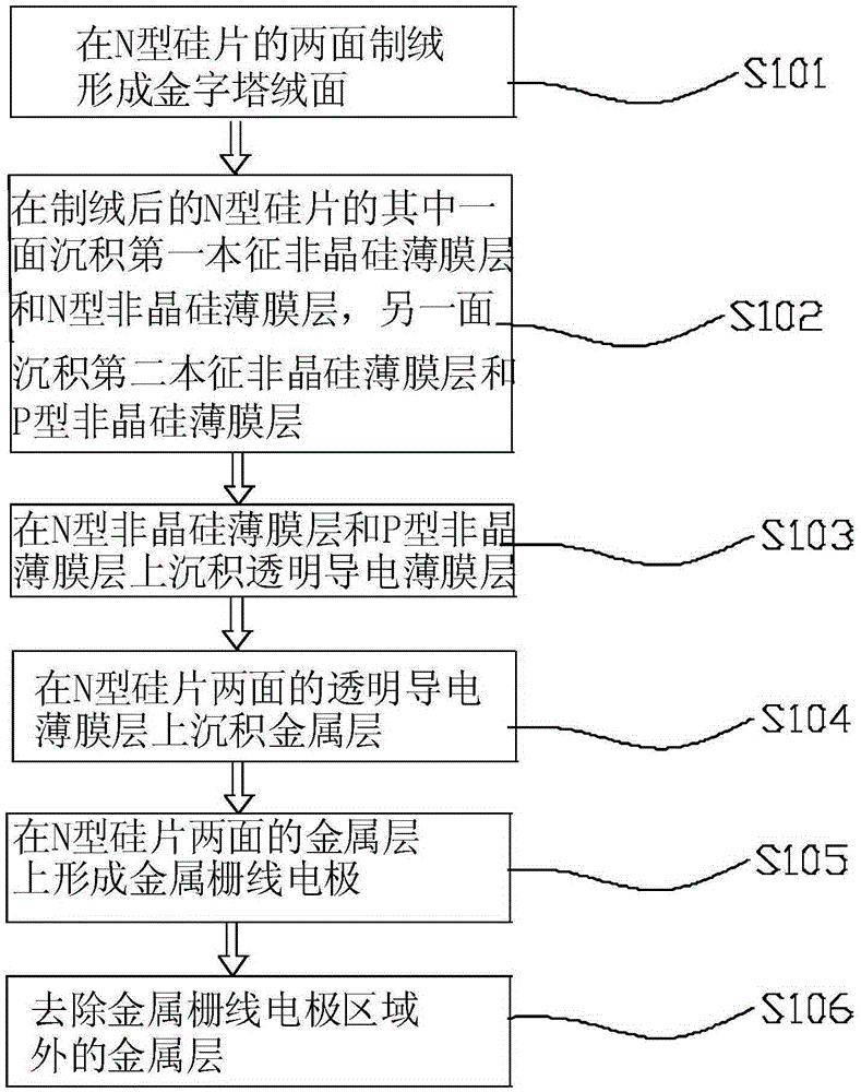
[0029] Such as figure 1 As shown, the present invention discloses a method for preparing a double-sided power generation heterojunction solar cell, which includes the following steps:

[0030] S101: making texture on both sides of the N-type silicon wafer to form a pyramid texture;

[0031] S102: Deposit a first intrinsic amorphous silicon thin film layer and an N-type amorphous silicon thin film layer on one side of the textured N-type silicon wafer, and deposit a second intrinsic amorphous silicon thin film layer and a P-type amorphous silicon thin film layer on the other side. Crystal silicon ...


PUM

PropertyMeasurementUnit
Thicknessaaaaaaaaaa
Thicknessaaaaaaaaaa
Thicknessaaaaaaaaaa

Abstract

The invention discloses a preparation method of a double-side power generation heterojunction solar cell. The method comprises that a) two sides of an N type silicon chip are textured to form pyramid suede; b) a first intrinsic amorphous silicon thin film layer and an N type amorphous silicon thin film layer are deposited at one side of the textured N type silicon chip, and a second intrinsic amorphous silicon thin film layer and a P type amorphous silicon thin film layer are deposited at the other side; c) transparent conductive thin film layers are deposited on the N type amorphous silicon thin film layer and the P type amorphous silicon thin film layer respectively; d) metal layers are deposited on the transparent conductive thin film layers at the two sides of the N type silicon chip; e) metal grid-line electrodes are formed on the metal layers at the two sides of the N type silicon chip; and f) metal layers beyond a metal-grid line electrode area are removed. According to the method, low-temperature metal makes good contact with transparent conductive films, high-molecular shielding layers in the edges of metal grid lines can be removed, the serial connection resistance of the cell can be reduced, effective absorption light of the solar cell is increased, and further, the conversion efficiency is improved.

Description

technical field [0001] The invention relates to the technical field of solar cells, in particular to a method for preparing a double-sided power generation heterojunction solar cell. Background technique [0002] A solar cell is a semiconductor device that can convert solar energy into electrical energy. Under the condition of light, a photogenerated current will be generated inside the solar cell, and the electrical energy will be output through the electrodes. In recent years, the production technology of solar cells has been continuously improved, the production cost has been continuously reduced, and the conversion efficiency has been continuously improved. The application of photovoltaic power generation has become increasingly widespread and has become an important energy source for power supply. [0003] Crystalline silicon solar cells have the advantages of high photoelectric conversion efficiency and mature production technology, and have always occupied the vast ma...

Claims


Application Information

Patent Timeline
IPC IPC(8): H01L31/0747H01L31/0224H01L31/18
CPCH01L31/022425H01L31/0747H01L31/1804Y02E10/547Y02P70/50
Inventor 杨与胜王树林宋广华罗骞庄辉虎张超华
Owner GS SOLAR CHINA COMPANY
Features
  • Generate Ideas
  • Intellectual Property
  • Life Sciences
  • Materials
  • Tech Scout
  • Unparalleled Data Quality
  • Higher Quality Content
  • 60% Fewer Hallucinations
Learn More