
Coal-fired boiler flue gas-catalytic regeneration flue gas combined discharging system

A technology for regenerating flue gas and coal-fired boilers, which is applied in the fields of climate change adaptation, climate sustainability, chemical instruments and methods, etc., and can solve problems such as optimal allocation of unfavorable resources, expansion of equipment footprint, and inability to meet flue gas emissions. , to achieve significant environmental benefits, reduce floor space, and reduce air pollution

Inactive Publication Date: 2017-05-03
CHINA PETROLEUM & CHEM CORP
View PDF6 Cites 4 Cited by
  • Summary
  • Abstract
  • Description
  • Claims
  • Application Information

AI Technical Summary

Problems solved by technology

[0003] SO2 in the desulfurized flue gas after the flue gas of the coal-fired boiler has been treated by limestone-gypsum wet flue gas desulfurization 2 400mg / Nm 3 , NO in flue gas X The concentration of 440mg / Nm 3 , the concentration of dust particles is 50mg / Nm 3 , can not meet the flue gas emission SO 2 The concentration is not more than 50mg / Nm 3 , NO X The concentration is not more than 100mg / Nm 3 , the concentration of dust particles is 20mg / Nm 3 new standard for
[0004] In the prior art, catalytic regeneration flue gas and coal-fired boiler flue gas are processed and discharged separately, which increases the processing equipment and expands the area occupied by the device, which is not conducive to the optimal allocation of resources.

Method used


Image

  • Coal-fired boiler flue gas-catalytic regeneration flue gas combined discharging system
  • Coal-fired boiler flue gas-catalytic regeneration flue gas combined discharging system
  • Coal-fired boiler flue gas-catalytic regeneration flue gas combined discharging system

Examples


Embodiment Construction

[0016] The present invention will be described in detail below in conjunction with the embodiments and the accompanying drawings. The protection scope of the present invention is not limited to the embodiments, and any changes made by those skilled in the art within the scope defined in the claims also belong to the protection scope of the present invention.

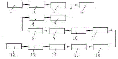
[0017] The coal-fired boiler flue gas-catalytic regeneration flue gas combined discharge system of the present invention, such as figure 1 As shown, it includes catalytic regeneration flue gas unit, coal-fired boiler flue gas unit and flue gas desulfurization device 4. The catalytic regeneration flue gas unit includes a catalytic flue gas waste heat boiler, 1, a catalytic flue gas dust collector 2 and a catalytic economizer 3. The catalytic flue gas waste heat boiler is connected to the catalytic flue gas waste heat boiler through the catalytic flue gas dust collector. The inlet is connected to the outlet of the catalyt...


PUM


Abstract

The present invention relates to a coal-fired boiler flue gas-catalytic regeneration flue gas combined discharging system, which comprises a catalytic regeneration flue gas unit, a coal-fired boiler flue gas unit and a flue gas desulfurization device, wherein the flue gas desulfurization device is provided with a chimney, the catalytic regeneration flue gas unit comprises a catalytic flue gas waste heat boiler, a catalytic flue gas dust collector and a catalytic economizer, the catalytic flue gas waste heat boiler is connected to the catalytic economizer through the catalytic flue gas dust collector, the coal-fired boiler flue gas unit comprises a steam boiler, a steam superheater, a high temperature economizer, a No.1 high temperature pre-heater, a No.2 high temperature pre-heater, a boiler flue gas low temperature economizer, a No.1 low temperature pre-heater, a denitrification device, No.2 low temperature pre-heater boiler, a boiler flue gas dust collector and an induced fan, the steam boiler, the steam superheater, the high temperature economizer, the No.1 high temperature pre-heater, the No.2 high temperature pre-heater, the boiler flue gas low temperature economizer, the No.1 low temperature pre-heater, the denitrification device, the No.2 low temperature pre-heater boiler, the boiler flue gas dust collector and the induced fan are sequentially connected, and the outlets of the catalytic economizer and the induced fan are connected to the flue gas desulfurization device. According to the present invention, the flue gas emission meets the emission standard so as to reduce the air pollution, protect the natural environment, beneficially optimize the resource allocation, reduce the production apparatus occupation area, and reduce the production cost of the enterprise.

Description

technical field [0001] The invention belongs to the technical field of waste gas treatment and discharge, and relates to a flue gas discharge system, in particular to a coal-fired boiler flue gas-catalytic regeneration flue gas combined discharge system. Background technique [0002] Exhaust gas emission from petrochemical refineries is one of the main factors of atmospheric environmental pollution. In addition to the flue gas generated during the petroleum processing process, the flue gas emitted by the refinery also includes the flue gas generated by coal-fired boilers. The flue gas generated during the petroleum processing process is mainly The flue gas generated during the catalyst regeneration (combustion) process of the catalytic cracking unit is the catalytic regeneration flue gas. The catalytically regenerated flue gas passes through the flue gas turbine to generate electricity, and the waste heat boiler generates steam to be discharged to the chimney. Catalytic reg...

Claims


Application Information

Patent Timeline
IPC IPC(8): B01D53/76B01D53/80B01D53/86B01D53/56B01D53/50B01D47/02B03C3/04
CPCY02A50/2351
Inventor 刘晓欣杨树卿安志强
Owner CHINA PETROLEUM & CHEM CORP
Features
  • Generate Ideas
  • Intellectual Property
  • Life Sciences
  • Materials
  • Tech Scout
  • Unparalleled Data Quality
  • Higher Quality Content
  • 60% Fewer Hallucinations
Learn More