
Control method for electric spark pulse power supply device

A technology of pulse power supply and control method, applied in circuits, manufacturing tools, electric processing equipment, etc., can solve problems such as affecting processing efficiency and processing quality, and inconvenient operation.

Active Publication Date: 2017-05-10
保时杰数控机床江苏有限公司
View PDF8 Cites 3 Cited by
  • Summary
  • Abstract
  • Description
  • Claims
  • Application Information

AI Technical Summary

Problems solved by technology

[0002] The output voltage of the pulse power supply used in electric discharge machine tools such as wire cutting machine tools and punching machine tools is preset. There is no automatic voltage regulation function during the EDM process. The feed speed of the carriage is the feed of the workpiece. The speed should match the voltage of the pulse power supply. If the feed speed is too fast, the workpiece will contact with the electrode to form a short circuit. If the feed speed is too slow, an open circuit will be formed between the workpiece and the electrode. Both phenomena will affect the processing efficiency and Processing quality; in order to maintain a reasonable gap between the electrode and the workpiece to generate spark discharge, the operator needs to repeatedly adjust the feed parameters according to the processing situation, which brings great inconvenience to the operation

Method used


Image

  • Control method for electric spark pulse power supply device
  • Control method for electric spark pulse power supply device
  • Control method for electric spark pulse power supply device

Examples


Embodiment Construction

[0018] The specific embodiment of the present invention will now be described in conjunction with the accompanying drawings.

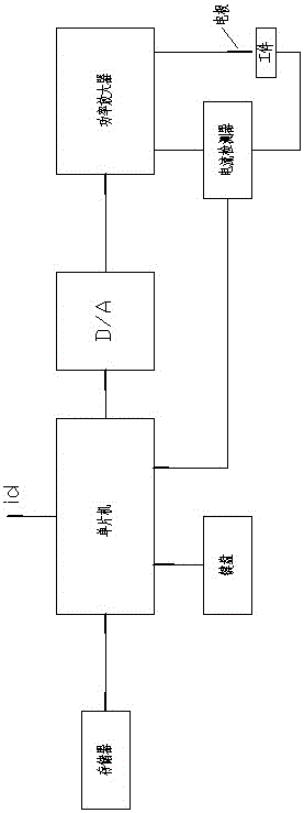
[0019] A control method for an electric spark pulse power supply device, the electric spark pulse power supply device includes a pulse signal generator composed of a single-chip microcomputer and a D / A converter, a power amplifier for power amplifying the pulse signal, and a power amplifier for detecting the power of the power amplifier. A current detector for output current, a memory for storing pulse signal information and output current information, and a keyboard for inputting data; its control method is realized by running the internal program of the single-chip microcomputer.

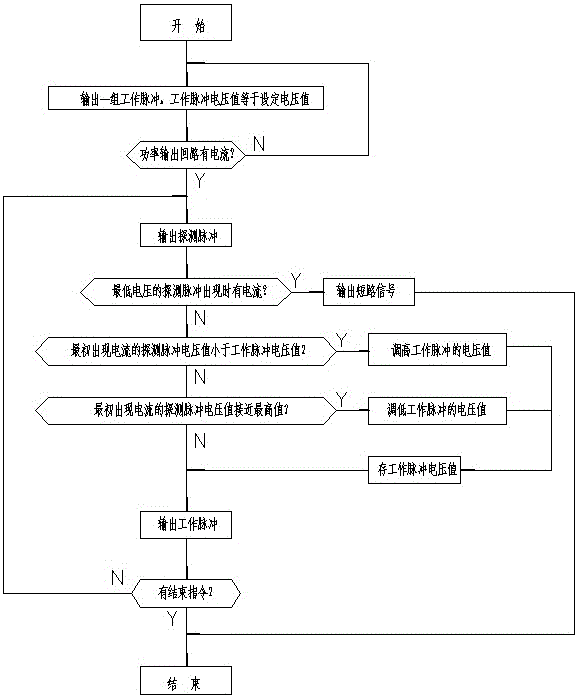
[0020] After starting up, the workpiece on the EDM machine moves to the electrode or the electrode moves to the workpiece at a certain speed;

[0021] Run the internal program of the single chip microcomputer (the program flow chart is as follows image 3 Shown), the prog...


PUM


Abstract

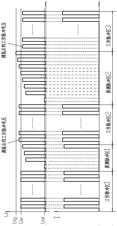
Disclosed is a control method for an electric spark pulse power supply device. The electric spark pulse power supply device comprises a pulse signal generator, a power amplifier and a current detector, wherein the pulse signal generator is composed of a single chip microcomputer and a D / A converter, the power amplifier is used for power amplifying of pulse signal, and the current detector is used for detecting output current of the power amplifier. The control method is realized through an internal program of the single chip microcomputer. The control method comprises the steps that probe pulses are inserted into a work pulse group at intervals; and voltage values of work pulses are adjusted automatically through the probe pulses to enable the voltage values of the work pulses to be matched with the speed of workpiece feeding. A state of spark discharge is kept, so that the phenomenon of short circuit is avoided, the probability of open circuit phenomenon occurring is reduced, machining efficiency and the machining quality are improved, and meanwhile, the inconvenience that adjusting of the cutting speed relies on manual work is removed. The short circuit is detected during occurrence of a low voltage detection pulse, so that damage to an electrode wire is avoided, and when a workpiece leaves an electrode, arcing is prevented, and decreasing of the finish degree of the workpiece is avoided.

Description

technical field [0001] The invention relates to a control method of an electric spark pulse power supply device. The control method enables the electric spark pulse power supply to output a suitable discharge voltage for electric spark machining. Background technique [0002] The output voltage of the pulse power supply used in electric discharge machine tools such as wire cutting machine tools and punching machine tools is preset. There is no automatic voltage regulation function during the EDM process. The feed speed of the carriage is the feed of the workpiece. The speed should match the voltage of the pulse power supply. If the feed speed is too fast, the workpiece will contact with the electrode to form a short circuit. If the feed speed is too slow, an open circuit will be formed between the workpiece and the electrode. Both phenomena will affect the processing efficiency and Processing quality; in order to maintain a reasonable gap between the electrode and the workpi...

Claims


Application Information

Patent Timeline
Patent Type & Authority Applications(China)
IPC IPC(8): B23H1/02
CPCB23H1/02
Inventor 丁毅
Owner 保时杰数控机床江苏有限公司
Learn More