Manufacturing technology of glass fiber/epoxy resin composite material substrate type fiber bragg grating sensor

An epoxy resin and glass fiber technology, applied in instruments, optical components, applications, etc., can solve the problems of poor sensor monitoring stability, poor sensor monitoring accuracy, high strength and stiffness, and achieve full curing, improve performance stability, The effect of high strength and stiffness

Active Publication Date: 2017-05-10
SHANDONG UNIV
View PDF2 Cites 15 Cited by
  • Summary
  • Abstract
  • Description
  • Claims
  • Application Information

AI Technical Summary

Problems solved by technology

Although the fiber grating sensor made of metal and resin as the substrate material has the advantages of simple structure and easy installation, the substrate material is generally thick, which is prone to strain transfer loss, resulting in poor monitoring accuracy and low sensitivity of the sensor. It is easy to debond from the substrate material, resulting in poor monitoring stability and short service life of the sensor; in addition, it is difficult for the fiber grating sensor made of metal and resin as the substrate material to have chemical corrosion resistance, high strength and rigidity, and shear resistance at the same time. Ability and other advantages

Method used


Image

  • Manufacturing technology of glass fiber/epoxy resin composite material substrate type fiber bragg grating sensor
  • Manufacturing technology of glass fiber/epoxy resin composite material substrate type fiber bragg grating sensor
  • Manufacturing technology of glass fiber/epoxy resin composite material substrate type fiber bragg grating sensor

Examples


Embodiment 1

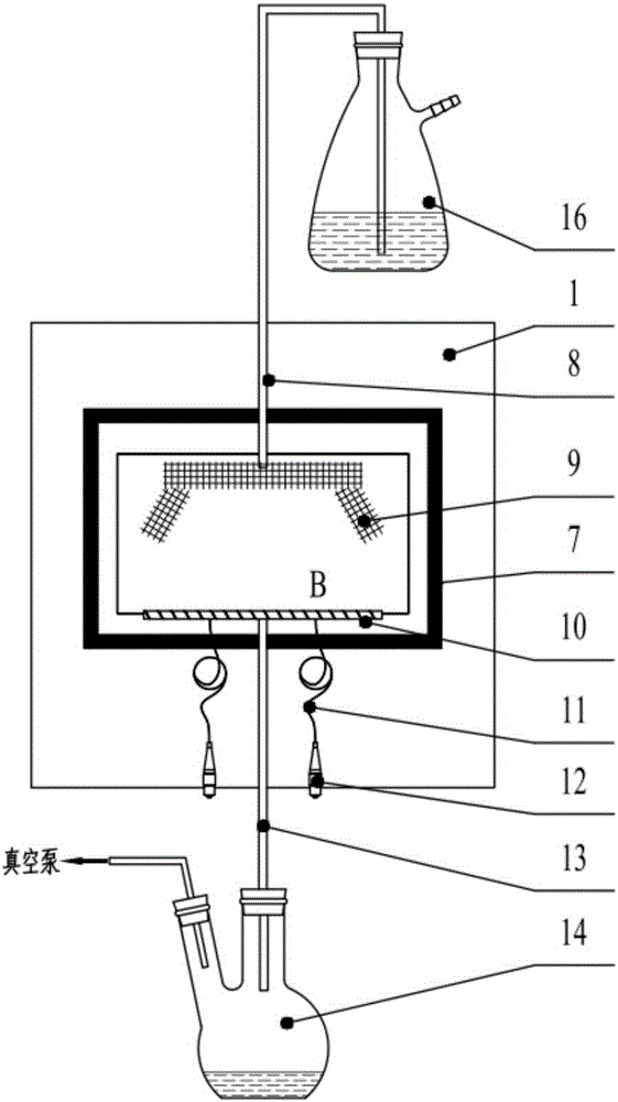
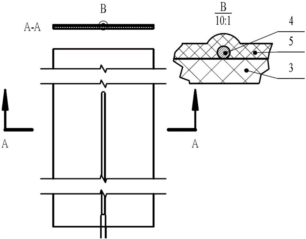
[0039] (1) Take three strained optical fibers with a single grating area, and coat them with polytetrafluoroethylene tubes respectively. The distance between the nozzle of the polytetrafluoroethylene tube and the grating area is kept at 3 cm, and the optical fiber and the polytetrafluoroethylene tube are placed at the nozzle. The gap between the tubes is glued so that the fiber grating can be straightened and fixed, and then the pigtail is fused with a transmission fiber 11 with a fiber connector 12 at one end and is ready for use.

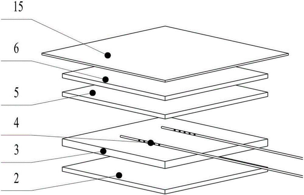
[0040] (2) Take two pieces of orthogonally woven glass fiber prepregs with a size of 250mm*150mm, align them and lay them flat, lay a layer of release cloth of the same size on the top and bottom, and then place them between two flat steel plates Pre-cure for 15 minutes at 130°C and 0.5MPa. After the pre-curing is completed, the release cloths on the upper and lower surfaces are removed to obtain a pre-cured glass fiber / epoxy resin composite subst...

Embodiment 2

[0051] The difference from Example 1 is that the strain fiber grating and the temperature fiber grating are laid adjacently and parallelly on the glass fiber / epoxy resin composite substrate.

Embodiment 3

[0053] The difference from Embodiment 1 is that the fiber grating string is laid on the glass fiber / epoxy resin composite material substrate.


PUM

PropertyMeasurementUnit
thicknessaaaaaaaaaa

Abstract

The invention discloses a manufacturing technology of a glass fiber/epoxy resin composite material substrate type fiber bragg grating sensor. The manufacturing technology comprises the steps that glass fiber/epoxy resin prepreg is procured to prepare a glass fiber/epoxy resin composite material substrate; a fiber bragg grating is fixed to the glass fiber/epoxy resin composite material substrate; the glass fiber/epoxy resin composite material substrate fixed with the fiber bragg grating is covered with a dry-state glass fiber cloth, vacuum aided filling of liquid epoxy resin is performed, and secondary curing molding is performed. The manufacturing technology adopts the secondary curing molding in the packaging process, the interlayer interface strength is remarkably improved, accordingly the testing precision and stability of the fiber bragg grating sensor are improved, batch production of the fiber bragg grating sensor can be achieved, and the manufacturing technology has wide market prospect and huge economic benefit.

Description

technical field [0001] The invention relates to a manufacturing process of a glass fiber / epoxy resin composite material substrate type fiber grating sensor, in particular to a method of pre-curing through glass fiber / epoxy resin prepreg, vacuum assisted infusion of epoxy resin and high temperature secondary Curing process for fabricating glass fiber / epoxy resin composite substrate-based fiber grating sensors. Background technique [0002] Fiber Bragg Grating is a new type of optical passive device, which can change or control the propagation behavior and mode of light in this area by establishing a periodic refractive index distribution in the axial direction of the fiber. Compared with traditional electromechanical sensors, sensors using fiber gratings as sensing elements have the advantages of light weight, high sensitivity, corrosion resistance, anti-electromagnetic interference, and in-situ online monitoring for a long time, so they can be used in civil engineering , ai...

Claims


Application Information

Patent Timeline
Patent Type & Authority Applications(China)
IPC IPC(8): C08J5/24C08J5/04C08L63/02C08G59/50G01D21/02B29C70/36B29L11/00
CPCB29C70/36B29L2011/0066C08G59/5006C08J5/043C08J5/24C08J2363/00G01D21/02
Inventor 贾玉玺王庆林高琳琳张晨郭云力姜明顺王海庆智杰颖赵亚如隋青美
Owner SHANDONG UNIV
Why Eureka
Try Eureka