Hydrothermal liquidization system and hydrothermal liquidization method for biomass

A technology for hydrothermal liquefaction and biomass, which is applied in the preparation of liquid hydrocarbon mixture, petroleum industry, processing of hydrocarbon oil, etc., can solve the problems of difficulty in realizing continuous reaction with continuous feeding and unfavorable large-scale production of biomass hydrothermal liquefaction.

Active Publication Date: 2017-05-10
ENN SCI & TECH DEV
View PDF5 Cites 2 Cited by
  • Summary
  • Abstract
  • Description
  • Claims
  • Application Information

AI Technical Summary

Problems solved by technology

[0003] However, in the process of biomass liquefaction reaction, because the reaction temperature and reaction pressure in the reactor are usually difficult to maintain in the required range of liquefaction reaction during the continuous feeding and continuous discharging process (that is, the temperature requireme

Method used


Image

  • Hydrothermal liquidization system and hydrothermal liquidization method for biomass
  • Hydrothermal liquidization system and hydrothermal liquidization method for biomass
  • Hydrothermal liquidization system and hydrothermal liquidization method for biomass

Examples


Embodiment 1

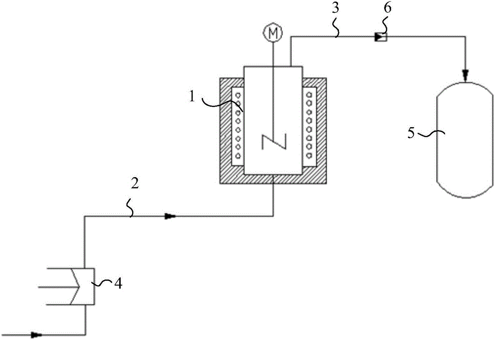
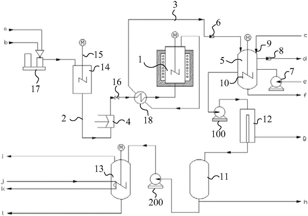
[0075] Taking silk algae (algae filament length 80cm) as an example to carry out the liquefaction test, it specifically includes the following test steps: first, mix the silk algae and deionized water in a ratio of 3:17, and add the crushing device to crush the material into The slurry with a particle size less than or equal to 1mm enters the material storage device and is ready for use; then, feed deionized water into the tubular reactor through the feed pipe and high-pressure plunger pump to preheat the tubular reactor, and at the same time pass the product The discharge pipe discharges the preheated product. When the temperature in the tubular reactor reaches 330°C and the pressure reaches 20MPa, start to replace the deionized water with the spare slurry, and open the stirring device in the material storage device and the outlet at the bottom of the material storage device. The material inlet valve is used to feed the slurry into the high-pressure plunger pump, and the outle...

Embodiment 2

[0078]The liquefaction test was carried out with coccus (3-8um in diameter) as an example, which specifically included the following test steps: mix coccus and deionized water at a ratio of 2:8 to form a slurry, and add it to the material storage device for standby; then , feed deionized water into the reactor through the feed pipe and high-pressure plunger pump to preheat the reactor, and at the same time discharge the preheated product through the product discharge pipe. When the temperature in the reactor reaches 330°C and the pressure reaches 20MPa, Start to replace deionized water with spare slurry, and open the stirring device in the material storage device and the outlet valve at the bottom of the material storage device to pass the slurry into the high-pressure plunger pump, and open the outlet of the high-pressure plunger pump The valve is used to feed the slurry into the reactor, and at the same time adjust the opening of the flow regulating valve, so that the system ...

Embodiment 3

[0081] Taking sludge as an example to carry out the liquefaction test, it specifically includes the following test steps: Concentrate the sludge to a water content of about 85%, and add a crushing device to crush the material into a slurry with a particle size of less than or equal to 1mm before entering the material The storage device is ready for use; then, pass deionized water into the reactor through the feed pipe and high-pressure plunger pump to preheat the reactor, and at the same time discharge the preheated product through the product discharge pipe, when the temperature in the reactor reaches 330 ° C , the pressure reaches 20MPa, start to replace the deionized water with spare slurry, and open the stirring device in the material storage device and the outlet valve at the bottom of the material storage device to pass the slurry into the high-pressure plunger pump and turn on the high-pressure The outlet valve of the plunger pump is used to feed the slurry into the reac...


PUM

PropertyMeasurementUnit
Particle sizeaaaaaaaaaa

Abstract

The invention discloses a hydrothermal liquidization system and a hydrothermal liquidization method for biomass, relates to the technical field of biomass energy and aims to solve the problem that the hydrothermal liquidization system for the biomass in the prior art difficultly carries out continuous reaction of continuous feeding and continuous discharging. The hydrothermal liquidization system for the biomass provided by the invention comprises a reactor, a product collector and a flow control structure, wherein a feeding pipe and a product discharging pipe are connected to the reactor; a pressurizing device is serially connected onto the feeding pipe; the product collector is hermetically connected with the exhaust end of the product discharging pipe; the flow control structure is arranged between the product collector and the reactor and is used for controlling the flow, discharging to the product collector from the product discharging pipe, of the product, so that the discharging flow of the product discharging pipe is equal to the feeding flow of the feeding pipe. The hydrothermal liquidization system for the biomass, disclosed by the invention, is used for carrying out the continuous reaction of the continuous feeding and the continuous discharging.

Description

technical field [0001] The invention relates to the technical field of biomass energy, in particular to a biomass hydrothermal liquefaction system and method. Background technique [0002] Biomass hydrothermal liquefaction technology refers to the use of thermochemical methods to convert biomass (such as silk algae, coccus, sludge, peanut straw, Pig manure, etc.) raw materials into the process of biomass oil. Biomass hydrothermal liquefaction technology is a promising biomass oil production technology with many advantages. First, compared with traditional thermochemical conversion technologies (such as gasification and pyrolysis), biomass hydrothermal liquefaction technology can directly convert undried wet biomass into energy-dense biomass oil, thus avoiding the additional cost of drying process. High energy consumption, so it has a lower energy consumption rate, especially suitable for processing wet biomass such as biomass. Secondly, biomass hydrothermal liquefaction t...

Claims


Application Information

Patent Timeline
IPC IPC(8): C10G1/00
CPCC10G1/002C10G1/008C10G2300/1011
Inventor 白秀军刘敏胜刘轶辰杨巧利侯祥生刘元杰白雪梅
Owner ENN SCI & TECH DEV
Why Eureka
Try Eureka