Bipolar solid ablation type plasma accelerator

A plasma and accelerator technology, applied in the field of space electric propulsion devices, can solve problems such as low efficiency of accelerators, and achieve the effects of simple structure, improved utilization efficiency, and reduced complexity

Active Publication Date: 2017-05-10
BEIJING RES INST OF PRECISE MECHATRONICS CONTROLS
View PDF5 Cites 16 Cited by
  • Summary
  • Abstract
  • Description
  • Claims
  • Application Information

AI Technical Summary

Problems solved by technology

[0005] The object of the present invention is a high-efficiency bipolar solid ablation plasma accelerator for in-orbit pro

Method used


Image

  • Bipolar solid ablation type plasma accelerator

Examples


Example Embodiment

[0024] The present invention will be further described in detail below with reference to the drawings and embodiments.

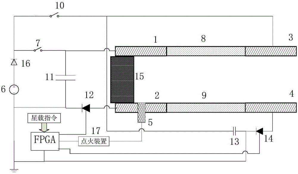
[0025] Such as figure 1 As shown, a bipolar solid ablation plasma accelerator provided by the present invention includes a first anode 1 and a first cathode 2, a second anode 3 and a second cathode 4, a spark plug 5, a DC power supply 6, and a main high voltage control Switch 7, primary insulating material 8, secondary insulating material 9, secondary high voltage control switch 10, primary discharge capacitor 11, primary thyristor 12, secondary discharge capacitor 13, secondary thyristor 14, solid propellant 15, and diode 16. The anode of the DC power supply 6 is connected to the anode of the diode 16, and the cathode of the diode 16 is connected to one end of the main high voltage control switch 7 and the secondary high voltage control switch 10 respectively. The DC power supply 6 supplies power to the main discharge capacitor 11 through the main high voltag...


PUM


Abstract

The invention belongs to a space electric propulsion device, and particularly discloses a bipolar solid ablation type plasma accelerator. A positive pole of a direct-current power supply of the accelerator is connected with one end of each of a primary high-voltage control switch and a secondary high-voltage control switch; the other end of the primary high-voltage control switch is connected with one end of each of a primary discharge capacitor and a primary electrode; the other end of the primary discharge capacitor is connected with each of a negative pole of the direct-current power supply and a cathode of a primary silicon controlled rectifier; an anode of the primary silicon controlled rectifier is connected with the other end of the primary electrode; the other end of the secondary high-voltage control switch is connected with one end of each of a secondary discharge capacitor and a secondary electrode; the other end of the secondary discharge capacitor is connected with each of the negative pole of the direct-current power supply and a cathode of the secondary silicon controlled rectifier; and an anode of the secondary silicon controlled rectifier is connected with the other end of the secondary electrode. According to the device, the problem of low efficiency of the solid ablation type plasma accelerator can be effectively solved.

Description

technical field [0001] The invention belongs to a space electric propulsion device, in particular to a high-efficiency bipolar solid ablation plasma accelerator for in-orbit propulsion of microsatellites. Background technique [0002] Microsatellites (10-100Kg) have broad application prospects in the fields of low-cost space experiments, communications, earth observation, navigation and positioning due to their low cost, short development period, easy networking, flexible launch and high payload. Since the beginning of the 21st century, with the development of current high technologies such as microelectronics technology, micro-processing and new material development technology, the research on micro-satellites has gradually heated up, and the proportion of the number of space launches has shown a rapid increase. However, due to the limitation of overall power and mass, the propulsion technology of microsatellites in orbit requires the propulsion system to have the character...

Claims


Application Information

Patent Timeline
IPC IPC(8): F03H1/00
CPCF03H1/00
Inventor 杨磊黄玉平曾广商杨斌闫丽媛
Owner BEIJING RES INST OF PRECISE MECHATRONICS CONTROLS
Why Eureka
Try Eureka