Coal-fired power plant smoke dehumidification system and technology

A coal-fired power plant, flue gas technology, applied in the direction of climate sustainability, combustion technology mitigation, greenhouse gas reduction, etc. High problems, to achieve the effect of reducing failure rate and investment cost, reducing cooling water spray, and improving desulfurization efficiency

Active Publication Date: 2017-05-10
HUADIAN ELECTRIC POWER SCI INST CO LTD
View PDF8 Cites 5 Cited by
  • Summary
  • Abstract
  • Description
  • Claims
  • Application Information

AI Technical Summary

Problems solved by technology

However, GGH has a high investment cost (accounting for about 15% of the total investment of the entire desulfurization system), and it is easy to block, have large resistance and high failure rate during operation, and has been gradually eliminated by power plants; chimneys such as lining titanium plates and lining foam glass bricks Anti-corrosion technology construction is difficult and expensive
[0004] In the Chinese patent with publication number CN 105413430A, a wet flue gas desulfurization tower with deep dehumidification function and a dehumidification process are disclosed. The dehumidification process sprays calcium chloride, lithium chloride, etc. The dehumidification working fluid is used to achieve the purpose of flue gas dehumidification and reheating, but the flue gas will carry part of the dehumidification working fluid into the chimney, causing secondary pollution, and the quality of the spraying process is large, and the regeneration of the dehumidification working fluid consumes a lot of energy, and the flue gas regenerates thermal effect is not obvious
In the Chinese patent with the publication number CN 105536450A, a flue gas dehumidification process is disclosed. The dehumidification process adds a circulating dehumidifier between the desulfurization island and the flue gas reheater, but the structure of the dehumidifier is a plurality of conical funnels. The desiccant Flowing in the funnel and contacting the flue gas, the desiccant is not in sufficient contact with the flue gas, which affects the dehumidification effect of the flue gas
[0005] To sum up, there is currently no flue gas dehumidification process and system with reasonable design and reliable performance to replace GGH, reduce the relative humidity of saturated wet flue gas after desulfurization, and prevent the phenomenon of "white smoke" and "gypsum rain" The appearance of the chimney can also inhibit the low-temperature corrosion of the chimney

Method used


Image

  • Coal-fired power plant smoke dehumidification system and technology
  • Coal-fired power plant smoke dehumidification system and technology
  • Coal-fired power plant smoke dehumidification system and technology

Examples


Embodiment Construction

[0024] The present invention will be further described in detail below in conjunction with the accompanying drawings and examples. The following examples are explanations of the present invention and the present invention is not limited to the following examples.

[0025] Example.

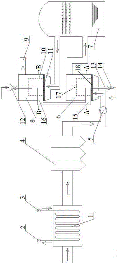
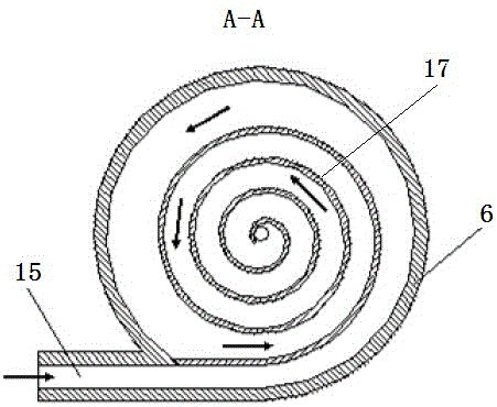
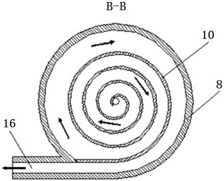
[0026] see Figure 1 to Figure 3 , the flue gas dehumidification system of a coal-fired power plant in this embodiment includes a low-temperature economizer 1, a low-temperature dust collector 4, a booster fan 5, a desiccant regenerator 6, a desulfurization tower 7, and a flue gas dehumidifier 8. Low-temperature coal-saving Device 1, low and low temperature dust collector 4, booster fan 5, desiccant regenerator 6, desulfurization tower 7 and flue gas dehumidifier 8 are connected in sequence along the flue gas flow direction.

[0027]The heat exchange tube inlet 3 in the low temperature economizer 1 in this embodiment is connected to the condenser, the heat exchange tube outlet 2 in the low tempera...


PUM


Abstract

The invention relates to a coal-fired power plant smoke dehumidification system and technology. At present, no system which can prevent white smoke and gypsum rain and restrain low-temperature corrosion of a chimney exists. The system comprises a low-temperature economizer, a low-temperature dust remover, a pressurizing fan, a desulfurizing tower and a smoke dehumidifier. The system is characterized by further comprising a drying agent regenerator. A regenerator spiral plate annular channel and a regenerator air distributor are arranged in the drying agent regenerator. The regenerator spiral plate annular channel is installed in the regenerator air distributor. The smoke dehumidifier is provided with a dehumidifier spiral plate annular channel and a dehumidifier air distributor. The dehumidifier spiral plate annular channel is installed in the dehumidifier air distributor. A drying agent outlet in the smoke dehumidifier is connected with a drying agent inlet in the drying agent regenerator to form a circular dehumidification device. The system avoids formation of the white smoke and the gypsum rain, and greatly weakens corrosion to the chimney.

Description

technical field [0001] The invention relates to a flue gas dehumidification system and process of a coal-fired power plant, which can recover the waste heat of low-temperature flue gas, reduce the water consumption of the desulfurization system, reduce the relative humidity of the exhausted flue gas, and inhibit the corrosion of the chimney, belonging to the cross field of energy technology and environmental protection technology . Background technique [0002] As my country's environmental protection standards become increasingly stringent, the "Comprehensive Implementation of Ultra-low Emissions and Energy-Saving Transformation Work Plan for Coal-fired Power Plants" (Huanfa [2015] No. 164) puts forward new requirements for the emission limits of soot, sulfur dioxide and nitrogen oxides , during the "13th Five-Year Plan" period, all coal-fired power plants will undergo ultra-low emission transformation, and the emission limits of soot, sulfur dioxide and nitrogen oxides must...

Claims


Application Information

Patent Timeline
Patent Type & Authority Applications(China)
IPC IPC(8): F23J15/02F23J15/06F22D1/00B01D53/26
CPCB01D53/263F22D1/003F23J15/02F23J15/06Y02E20/30
Inventor 王帅张庆国颜喜王凯
Owner HUADIAN ELECTRIC POWER SCI INST CO LTD
Why Eureka
Try Eureka