Optical fiber micro-bubble Fabry-Perot sensor and sensing method thereof

A Fab sensor and sensor technology, applied in the field of optical fiber, can solve the problems of high production difficulty, complex production process, high cost, etc., and achieve the effects of integration, flexible control, and fixed-point measurement

Active Publication Date: 2017-05-10
UNIV OF ELECTRONICS SCI & TECH OF CHINA
View PDF5 Cites 13 Cited by
  • Summary
  • Abstract
  • Description
  • Claims
  • Application Information

AI Technical Summary

Problems solved by technology

[0004] The object of the present invention is to provide optical fiber micro-bubble method peroxide sensor and sensing method thereof, in order to overcome the defects of existing optical fiber method peroxide cavity sensor complex structure, complex manufacturing process, extremely difficult manufacture and high cost; A uniform carbon nano-film is deposited on the fiber core of the flat end face of the optical fiber to form an optical fiber microbubble F-P sensor; when the sensor is immersed in water, the light energy provided by the laser is transmitted through the single-mode optical fiber, exits from the end face of the optical fiber, and irradiates the carbon nano-film. , due to the good heat transfer performance of carbon nanotubes, a microbubble is formed at the carbon nanotube film, that is, the microbubble Fab cavity

Method used


Image

  • Optical fiber micro-bubble Fabry-Perot sensor and sensing method thereof
  • Optical fiber micro-bubble Fabry-Perot sensor and sensing method thereof
  • Optical fiber micro-bubble Fabry-Perot sensor and sensing method thereof

Examples


Embodiment 1

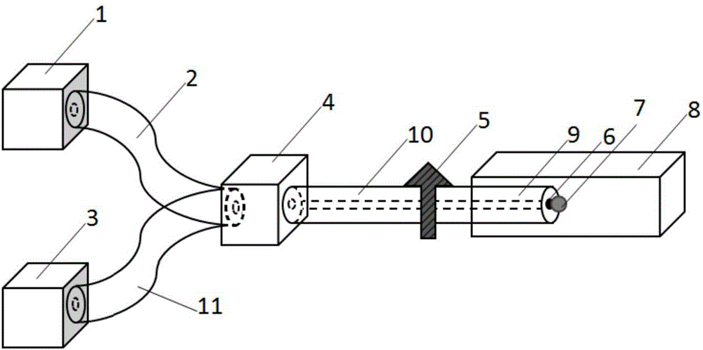
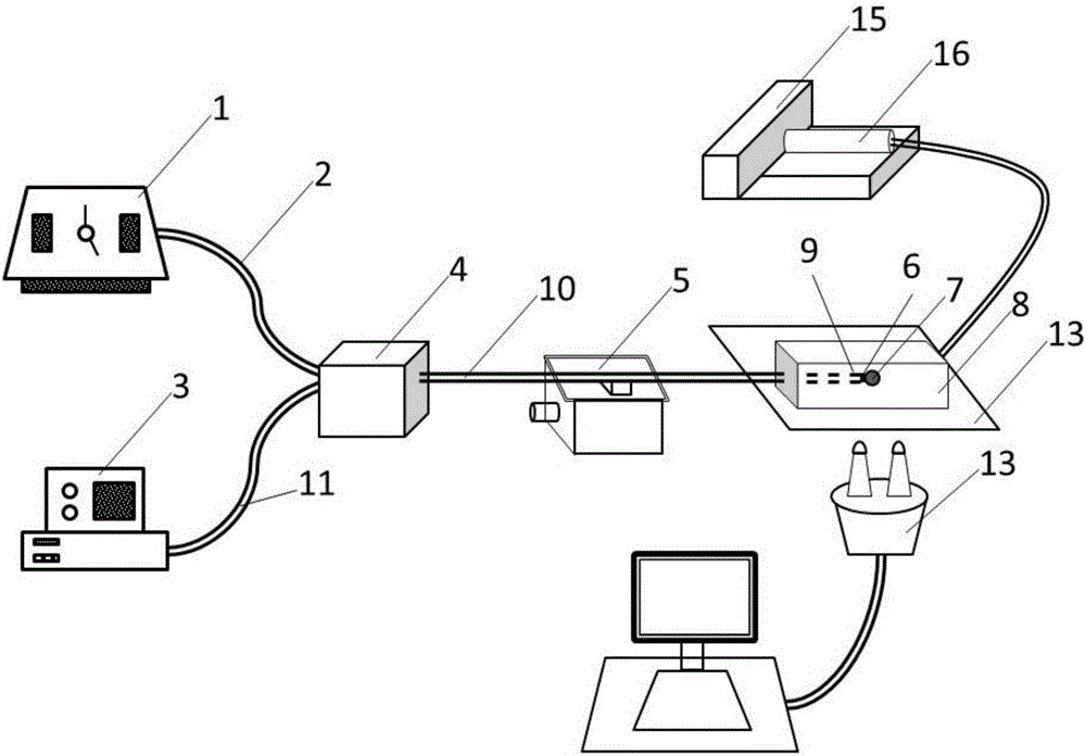
[0027] The sensing device of the fiber optic microbubble Fab sensor provided in this embodiment has a structure such as figure 1 As shown, it includes 980nm laser 1, front section HI 1060 single-mode fiber 2, common single-mode fiber 11, spectrum analyzer 3, wavelength division multiplexer 4, displacement stage 5, microfluidic channel 8 and sensor 9, sensor 9 is composed of The rear section is composed of HI 1060 single-mode fiber and carbon nano-film 6 uniformly deposited on the core of the flat end face of the single-mode fiber.

[0028] Among them, the common single-mode fiber 11 is a single-mode fiber with a central wavelength of 1550nm, the fiber core is very thin, the core diameter is generally 8 to 10um, and the cladding diameter is 125um, which is a commonly used single-mode fiber in the communication band;

[0029] The front section HI 1060 single-mode fiber 2 and the rear section HI 1060 single-mode fiber 10 are single-mode fibers with a center wavelength of 980nm, a...

Embodiment 2

[0035] This embodiment is further limited on the basis of Embodiment 1. The sensor 9 is a uniform carbon nanotube film 6 plated at the core of the end face of the cut flat rear section HI1060 single-mode optical fiber. According to the heat conduction characteristics of carbon nanotubes, Microbubbles 7 are generated in the liquid environment, which is the optical resonant cavity structure for sensing. Most of the probe-type optical fiber sensors in the prior art adopt the method of micromachining on the end face of the optical fiber. The manufacturing process of these methods is complicated and difficult. Preparation time reduces costs.

Embodiment 3

[0037]The present embodiment also provides a method for preparing a Perth cavity sensor based on the microbubble method on the end face of an optical fiber, which specifically includes the following steps:

[0038] Step 1): Cut the end face of the rear section HI 1060 single-mode optical fiber 10 with a cladding diameter of 125um and a core diameter of 5.8um to obtain a flat end face of the optical fiber;

[0039] Step 2): vertically insert the rear HI 1060 single-mode optical fiber 10 into the uniform carbon nanotube solution, and fix it;

[0040] Step 3): Turn on the 980nm laser 1, and adjust the power to 67.5mw. Under this power, slowly pull out the rear HI1060 single-mode fiber 10 vertically from the carbon nanotube solution, that is, finish once on the flat end surface of the fiber. The operation of coating carbon nano film;

[0041] Step 4): Repeat step 3) to perform multiple coating operations on the flat end face of the optical fiber to obtain a sensor.


PUM

PropertyMeasurementUnit
thicknessaaaaaaaaaa
wavelengthaaaaaaaaaa
poweraaaaaaaaaa

Abstract

The invention relates to the technical field of optical fibers, and particularly provides an optical fiber micro-bubble Fabry-Perot sensor and a sensing method thereof which are used for overcoming defects of complex structure, complicated production process, extremely high production difficulty and high cost of an existing optical fiber Fabry-Perot cavity sensor. According to the invention, a uniform carbon nano film is deposited at a fiber core on the flat end face of a single-mode optical fiber so as to form an optical fiber micro-bubble Fabry-Perot sensor; the sensor is immersed in a micro-flow system, light energy provided by a laser is transmitted through the single-mode optical fiber, emits through the end face of the optical fiber and irradiates on the carbon nano film, a micro-bubble is formed at the carbon nano film because a carbon nano tube has good heat transfer performance, and the micro-bubble is a micro-bubble Fabry-Perot cavity; and sensing for information of liquid environment factors such as the temperature and the flow rate is realized through detecting spectral information of the micro-bubble Fabry-Perot cavity. The sensor provided by the invention is simple in structure, and greatly reduces the preparation difficulty of an optical fiber end face microstructure. In addition, the optical fiber micro-bubble Fabry-Perot sensor is small in size, low in cost and flexible to operate.

Description

technical field [0001] The invention relates to the field of optical fiber technology, in particular to an optical fiber microbubble F-P sensor and a sensing method thereof. Background technique [0002] Compared with traditional sensing methods, fiber optic sensing has many irreplaceable advantages. Optical fiber sensors have high sensitivity, anti-electromagnetic interference, electrical insulation, high voltage resistance, corrosion resistance, and are suitable for harsh environments. Moreover, optical fiber sensors also have many advantages such as light weight, small size, bendable winding, and low cost, making them play an irreplaceable role in many fields such as petrochemical, electric power, medicine, and civil engineering. Among the many optical fiber sensor structures, the optical fiber FAP cavity sensor has attracted extensive attention in various fields because of its simple structure and good linearity. The fiber-optic F-P cavity sensor is based on the princi...

Claims


Application Information

Patent Timeline
Patent Type & Authority Applications(China)
IPC IPC(8): G01D5/26
CPCG01D5/268
Inventor 龚元张晨琳邹文亮饶云江
Owner UNIV OF ELECTRONICS SCI & TECH OF CHINA
Why Eureka
Try Eureka