Integrated double-layer vertical wound inductor and manufacturing method thereof

A manufacturing method and technology of inductors, applied in the field of inductors, can solve the problems of open circuit or short circuit of finished products, bumped coils, false welding, etc., and achieve the effect of enhancing load capacity guarantee, ensuring connection reliability and good performance.

Active Publication Date: 2017-05-10
GUANGDONG DECE TECH LTD
View PDF5 Cites 7 Cited by
  • Summary
  • Abstract
  • Description
  • Claims
  • Application Information

AI Technical Summary

Problems solved by technology

The flat-wire air-core coil traditionally used in one piece was originally similar to the assembled high-current flat coil. The side-wound single-layer coil is mostly used in low-inductance and high-current inductors, and the volume is larger than 6*6mm, which is not suitable for small-volume integral molding. High current inductor
In addition, the

Method used


Image

  • Integrated double-layer vertical wound inductor and manufacturing method thereof
  • Integrated double-layer vertical wound inductor and manufacturing method thereof
  • Integrated double-layer vertical wound inductor and manufacturing method thereof

Examples


Embodiment 1

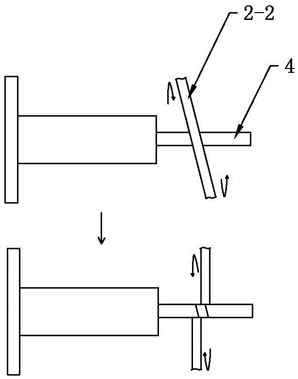
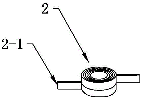
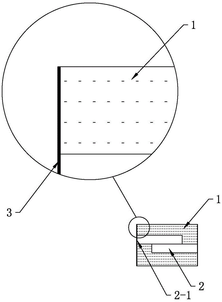
[0045] see Figure 1 to Figure 3 The integrated double-layer vertically wound inductor of this embodiment includes a magnetic body 1, an air-core coil 2 and a covered electrode 3. The magnetic body 1 is pressed from magnetic powder, and the air-core coil 2 is buried in the magnetic powder and passed through high The integral molding structure of the air-core coil 2 and the magnetic body 1 is obtained by pressing, the coil end 2-1 of the air-core coil 2 is exposed to the magnetic body 1, wherein the air-core coil 2 is provided with two layers of coils, and the winding directions of the upper and lower layers of coils are consistent and The upper and lower coils have the same number of turns. In this embodiment, the coil shape of the air-core coil 2 is circular. The air-core coil 2 has a layer of coils on the upper and lower layers, and the winding direction of the two-layer coils is exactly the same as the number of turns. This type of air-core coil 2 has a tighter structure, h...

Embodiment 2

[0066] The main technical solution of this embodiment is basically the same as that of Embodiment 1, and the features not explained in this embodiment are explained in Embodiment 1, and will not be repeated here. The coil shape of the air core coil 2 in this embodiment is ellipse.

Embodiment 3

[0068] The main technical solutions of this embodiment are basically the same as those of Embodiment 1 or Embodiment 2, and the features not explained in this embodiment are explained in Embodiment 1 or Embodiment 2, and will not be repeated here. In the manufacturing method of the integrated double-layer vertical wound inductor, the first stage of step (2) was sintered at 70°C for 30 minutes, the second stage was heated at 115°C for 90 minutes, and the third stage was sintered at 155°C for 30 minutes.


PUM


Abstract

The invention provides an integrated double-layer vertical wound inductor, which comprises a magnetic body, a hollow coil and a covered electrode, wherein the magnetic body is formed by pressing magnetic powder; the hollow coil is embedded into the magnetic powder and an integrated structure of the hollow coil and the magnetic body is manufactured through high pressure; the end part of the hollow coil is exposed out of the magnetic body; and the surface of one side, out of which the hollow coil is exposed, of the magnetic body is covered with the covered electrode. Compared with the prior art, the integrated double-layer vertical wound inductor has the advantages of being small in volume, good in performance, high in performance-volume ratio and beneficial to high-density installation, and the integration level of a client is improved. A manufacturing method of the integrated double-layer vertical wound inductor comprises the following steps of (1) carrying out compression molding; (2) carrying out multi-stage temperature sintering and solidifying; (3) adding an anti-oxidation coating; (4) grinding the end surfaces of two sides from which a lead of the hollow coil extends outside; (5) forming symmetrical boning pad positions on the upper surface and the lower surface of a semi-finished product; and (6) arranging the covered electrode.

Description

technical field [0001] The invention relates to the technical field of inductors, in particular to an integrated double-layer vertically wound inductor and a manufacturing method thereof. Background technique [0002] An inductor is an indispensable component of an electronic circuit. It plays the role of filtering, choking and energy storage in the circuit. It is composed of a conductor coil and a magnetic conductor, and the coil is a necessary part of the inductor. The coil is an indispensable carrier of the physical quantity of inductance. Coils with different diameters, shapes, turns and winding methods will directly affect the overcurrent capability, inductance, Q value and temperature resistance level of the inductor. There are mainly two types of coils used in one-piece molding, round copper wire hollow coils and flat wire hollow coils. Among them, the hollow coils wound by round copper wires are generally wound in a single method. The only difference is the size of t...

Claims


Application Information

Patent Timeline
IPC IPC(8): H01F27/255H01F27/28H01F27/29H01F27/34H01F27/36H01F41/00
CPCH01F27/255H01F27/28H01F27/292H01F27/346H01F27/36H01F41/00
Inventor 唐建伟汪民
Owner GUANGDONG DECE TECH LTD
Why Eureka
Try Eureka