Material continuous pyrolysis gasification device

A technology of pyrolysis gasification and materials, which is applied in the gasification of granular/powdered fuels, the manufacture of combustible gases, and the petroleum industry. It can solve the problems of limited space and increased costs, and achieve the effect of increasing the processing capacity.

Active Publication Date: 2019-06-11
SINOPEC DALIAN RES INST OF PETROLEUM & PETROCHEMICALS CO LTD +1
View PDF8 Cites 0 Cited by
  • Summary
  • Abstract
  • Description
  • Claims
  • Application Information

AI Technical Summary

Problems solved by technology

However, the arrangement of the microwave source in this method is limited to the lower part of the reaction chamber, and the space is limited. To realize flash pyrolysis cracking, it is necessary to equip a high-power magnetron to increase the microwave field strength, which will greatly increase the cost.

Method used


Image

  • Material continuous pyrolysis gasification device
  • Material continuous pyrolysis gasification device
  • Material continuous pyrolysis gasification device

Examples


preparation example Construction

[0045] The preparation of the catalyst used in the embodiment

[0046]Using the method of dry ball milling, nickel oxide, potassium hydroxide and biocoke generated during the pyrolysis process were mixed according to the mass ratio of 1:1:10, and ball milled at a speed of 150 rpm for 2 hours to obtain uniform charcoal Powdered catalyst, then cold pressed into strip particles, the size is φ4mm×6mm, the obtained catalyst is defined as NiO 1.0 KOH 1.0 / C 10 , where the NiO content is 8.33%, and the KOH content is 8.33%.

Embodiment

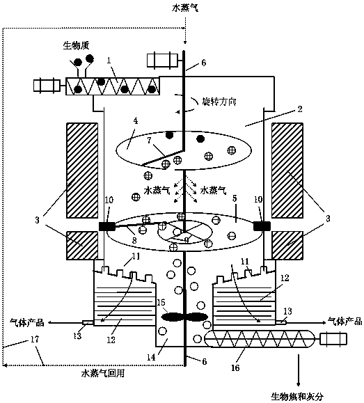
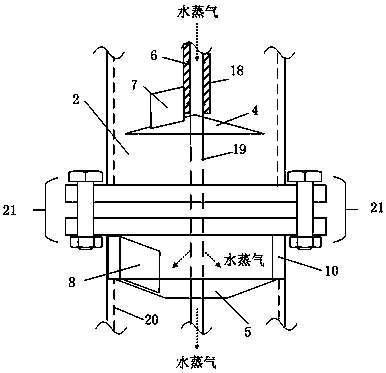
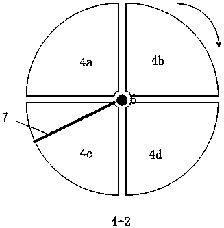
[0048] Biomass raw material and microwave catalyst NiO 1.0 KOH 1.0 / C 10 According to the ratio of 15:1, it is sent into the microwave reaction chamber 2 through the screw feeder 1, and falls into the first-stage rotating disk 4 under the action of gravity (the diameter of the bottom surface of the cone is 3 / 5 of the inner diameter of the microwave reaction chamber, and the conical busbar and the horizontal direction The included angle is 15°), when the first-stage rotating disk 4 is basically covered with materials, simultaneously rotate the first-stage rotating disk 4 and the second-stage rotating disk 5 (the diameter of the bottom surface of the round platform is 19 / of the inner diameter of the microwave reaction chamber 20. The diameter of the upper bottom surface of the round table is 1 / 4 of the inner diameter of the microwave reaction chamber, and the angle between the busbar of the round table and the horizontal direction is 20°), under the action of the first-stage p...


PUM

PropertyMeasurementUnit
angleaaaaaaaaaa

Abstract

The invention discloses a continuous material pyrolysis gasification device which comprises a spiral feeder, a microwave reaction cavity, a microwave generator, a first-stage rotating disc, a second-stage rotating disc, a hollow rotating shaft, a screening plate, a settling chamber, a residue storage tank and a spiral residue discharge device, wherein the spiral feeder is positioned at the upper part of the microwave reaction cavity; the microwave generator is arranged outside the microwave reaction cavity; the first-stage rotating disc and the second-stage rotating disc are arranged inside the microwave reaction cavity; the two stages of rotating discs are fixed through the hollow rotating shaft; the bottom of the microwave reaction cavity takes the shape of a ring and consists of a screening plate which tilts downwards; the settling chamber is connected below the screening plate; a gas product outlet is formed in the settling chamber; a non-screening plate part at the bottom of the microwave reaction cavity communicates with the residue storage tank below; and the residue storage tank is internally provided with a stirrer and communicates with the spiral residue discharge device. The continuous material pyrolysis gasification device is high in pyrolysis speed, high in gasification efficiency, high in gas product quality, capable of meeting requirements of synthesizing liquid fuel, and good in application prospect.

Description

technical field [0001] The invention relates to a material continuous pyrolysis gasification device. Background technique [0002] Traditional heating methods use radiation, convection, and conduction to heat from the surface to the inside. In order to avoid excessive temperature gradients, the heating speed is often not too fast, and the components of the material cannot be selectively heated. Because microwaves can directly penetrate into the material, compared with traditional heating methods, microwave heating can achieve balanced heating inside and outside the material, which has the advantages of fast heating rate and high energy utilization efficiency, and microwave can treat components with different dielectric properties in the material. Selective heating is performed. Therefore, the particularity of microwave heating makes pyrolysis products have greater advantages compared with traditional gasification technology, and it is a promising material heating method. ...

Claims


Application Information

Patent Timeline
Patent Type & Authority Patents(China)
IPC IPC(8): C10J3/66C10J3/48
Inventor 王鑫张彪张庆军蔡海乐张长安刘继华乔凯
Owner SINOPEC DALIAN RES INST OF PETROLEUM & PETROCHEMICALS CO LTD
Why Eureka
Try Eureka