Adsorptive regeneration device with solid-liquid phase change matters and adsorptive regeneration process

A solid-liquid phase change and regeneration device technology, which is applied in the field of adsorption regeneration devices and adsorption regeneration technology, can solve the problems of increasing system complexity, difficulty in oil and gas desorption, and increasing operating costs, and achieve volume reduction, large heat absorption, and The effect of saving investment

Pending Publication Date: 2017-05-24
上海聚宸新能源科技有限公司
View PDF13 Cites 3 Cited by
  • Summary
  • Abstract
  • Description
  • Claims
  • Application Information

AI Technical Summary

Problems solved by technology

This will undoubtedly increase investment and increase system complexity
[0005] After the activated carbon absorbs oil and gas, the vacuum regeneration process is generally used to regenerate the activated carbon. During regeneration, the temperature of the adsorbent is lowered due to the volatilization of the adsorbed oil and gas, and the lowering of the temperature makes it difficult to desorb the oil and gas.
What's more serious is that for some high melting point substances such as benzene, due to evaporation and heat absorption during desorption, the temperature may drop to the freezing point of benzene and other high melting point substances, and the adsorbate crystallizes in the micropores of the activated carbon, causing the destruction of the micropores of the activated carbon. Make activated carbon "poisoned" invalid, therefore, when desorbing, it is often necessary to introduce heated air or nitrogen to avoid the crystallization of the adsorbate, so that the regeneration can be completed smoothly. , which undoubtedly increases energy consumption and operating costs

Method used


Image

  • Adsorptive regeneration device with solid-liquid phase change matters and adsorptive regeneration process
  • Adsorptive regeneration device with solid-liquid phase change matters and adsorptive regeneration process
  • Adsorptive regeneration device with solid-liquid phase change matters and adsorptive regeneration process

Examples


Embodiment 1

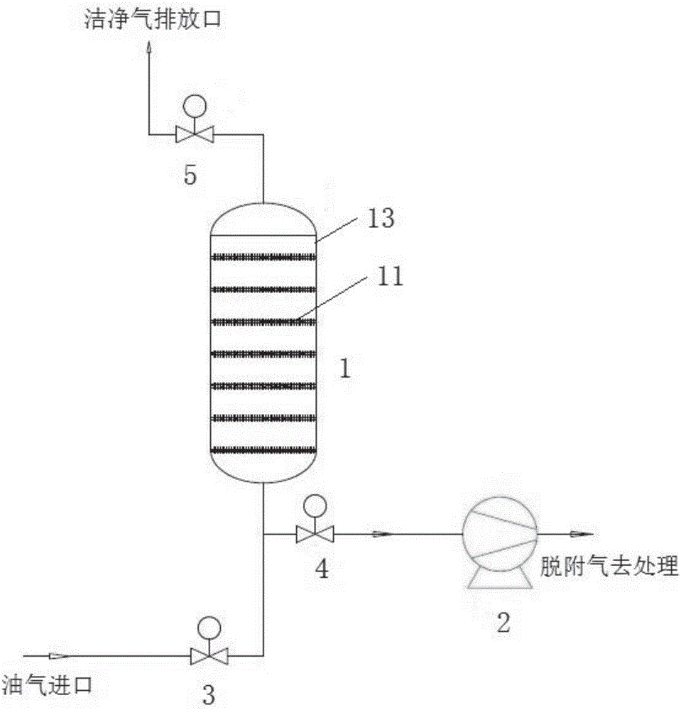
[0078] Such as figure 1 As shown, the present invention discloses an adsorption regeneration device with a solid-liquid phase change substance, including an oil gas inlet, a first adsorption tank 1, a first heat exchange tube 11, a vacuum pump 2, a first oil gas inlet valve 3, a first vacuum Valve 4, first oil and gas outlet valve 5, clean gas discharge port, wherein:

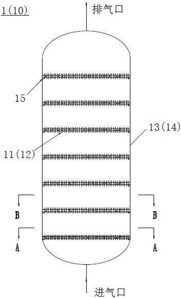
[0079] The first heat exchange tube 11 is arranged inside the first adsorption tank 1, and its inside is a hollow structure filled with a solid-liquid phase change energy storage material;

[0080] The oil and gas inlet is sequentially connected with the first oil and gas inlet valve 3, the first adsorption tank 1, the first oil and gas outlet valve 5 and the clean gas discharge port;

[0081] One end of the first vacuum valve 4 is connected between the first oil inlet valve 3 and the first adsorption tank 1 , and the other end is connected with the vacuum pump 2 .

[0082] Such as figure 2 As shown, the ad...

Embodiment 2

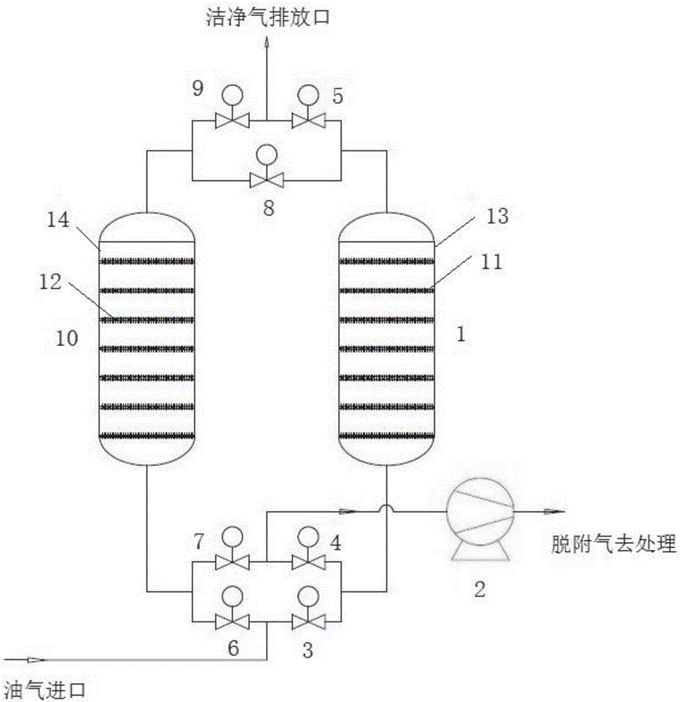
[0102] Such as Figure 6 As shown, the present invention also discloses an adsorption regeneration process with a solid-liquid phase change substance, comprising the following steps:

[0103] Step 1: The oil and gas to be treated enters through the oil and gas inlet, enters the first adsorption tank 1 through the first oil and gas inlet valve 3, and is absorbed and intercepted by the first adsorbent in the first adsorption tank 1, and the solid-liquid phase change substance passes through the fins The tube absorbs a large amount of adsorption heat to make the solid-liquid phase change material change from solid to liquid, stabilizing the adsorption temperature, and the remaining clean exhaust gas is heated by the remaining small amount of adsorption heat and then discharged into the atmosphere through the first oil and gas outlet valve 5, and the first adsorption tank 1 absorbs oil and gas At the same time, the second adsorption tank 10 is regenerating, and the alternating tim...

Embodiment 3

[0107] Such as Figure 7 As shown, the present invention additionally discloses an adsorption regeneration process with a solid-liquid phase change substance, comprising the following steps:

[0108] Step A: The oil and gas to be treated enter through the oil and gas inlet, the oil and gas enter the second adsorption tank 10 through the second oil and gas inlet valve 6, and are absorbed and intercepted by the second adsorbent in the second adsorption tank 10, and the solid-liquid phase change material passes through the fins The tube absorbs a large amount of adsorption heat to make the solid-liquid phase change material change from solid to liquid, stabilizing the adsorption temperature, and the remaining clean exhaust gas is heated by the remaining small amount of adsorption heat and then discharged into the atmosphere through the second oil and gas outlet valve 9, and the second adsorption tank 10 absorbs oil and gas At the same time, the first adsorption tank 1 is regenera...


PUM


Abstract

The invention discloses an adsorptive regeneration device with solid-liquid phase change matters and an adsorptive regeneration process. The device comprises an oil gas inlet, a first adsorption tank, a first heat exchange tube, a vacuum pump, a first oil inlet valve, a first vacuum valve, a first oil outlet valve and a clean gas discharge port, wherein the first heat exchange tube is arranged in the first adsorption tank and the inner portion of the first heat exchange tube is of a hollow structure and is filled with solid-liquid phase change energy storage matters; the oil gas inlet is successively connected to the first oil gas inlet valve, the first adsorption tank, the first oil gas outlet valve and a clean gas discharge port; and one end of the first vacuum valve is connected between the first oil gas inlet valve and the first adsorption tank while the other end is connected to the vacuum pump. The volume of a coil required is reduced in the adsorptive regeneration device with solid-liquid phase change matters, so that the field equipment is less, and the input cost is saved; and mechanical equipment such as a circulating pump and a switch valve is not used, so that the device is more stable to operate.

Description

technical field [0001] The invention relates to the technical field of oil and gas adsorption regeneration, in particular to an adsorption regeneration device with solid-liquid phase change material and an adsorption regeneration process. Background technique [0002] VOC gases such as oil and gas are generally discharged up to the standard through adsorption and other processes. Activated carbon with a large specific surface area is often used for adsorption. Since the adsorption process is an exothermic process, after activated carbon absorbs oil and gas, its ignition point may drop to about 100 ° C. Therefore, GB 50759 -2012 and other national standards require that the adsorption temperature be controlled within 65°C. If the temperature of the adsorption process is not well controlled, it will bring huge potential safety hazards. [0003] For the problem of adsorption temperature control, before the oil and gas enter the activated carbon adsorbent, the oil and gas are co...

Claims


Application Information

Patent Timeline
Patent Type & Authority Applications(China)
IPC IPC(8): B01D53/04
CPCB01D53/04B01D53/0454B01D2259/40083B01D2259/40086B01D2259/4009B01D2257/708
Inventor 白爽
Owner 上海聚宸新能源科技有限公司
Why Eureka
Try Eureka