Flue gas denitrification system and denitrification method for particle material industrial boiler

A technology for industrial boilers and granular materials, which is applied in the field of flue gas denitrification and can solve the problems that other methods are in the experimental research stage or pilot test stage.

Pending Publication Date: 2017-05-31
SHENWU TECH GRP CO LTD
View PDF0 Cites 3 Cited by
  • Summary
  • Abstract
  • Description
  • Claims
  • Application Information

AI Technical Summary

Problems solved by technology

There are many flue gas denitrification methods, but currently only the selective catalytic reduction method and the selective non-cataly

Method used


Image

  • Flue gas denitrification system and denitrification method for particle material industrial boiler
  • Flue gas denitrification system and denitrification method for particle material industrial boiler

Examples


preparation example Construction

[0096] According to a specific embodiment of the present invention, the preparation method of the denitration heat storage body specifically includes:

[0097] (1) Refining of heat storage body embryo body

[0098] Mix an appropriate amount of inorganic powder, ceramic powder, binder, plasticizing moisturizing agent, and lubricant, and add an appropriate amount of deionized water for kneading and refining to obtain mud material for use.

[0099] The mud block is aged, the temperature of the aging environment is 15-25°C, and the aging time is 24h-48h. After vacuum refining and vacuum extrusion, it is made into a honeycomb body blank of the required specification.

[0100] Then, the honeycomb body blank is sent to a dryer for shaping, drying, and firing at a temperature of 1200°C to 1400°C to obtain a finished product.

[0101] (2)TiO 2 -Al 2 o 3 Preparation of composite oxides

[0102] Take a certain amount of titanyl sulfate and aluminum chloride, dissolve them in an appr...

Embodiment

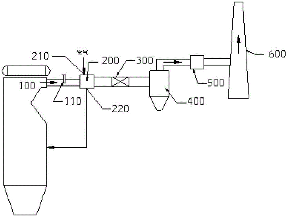
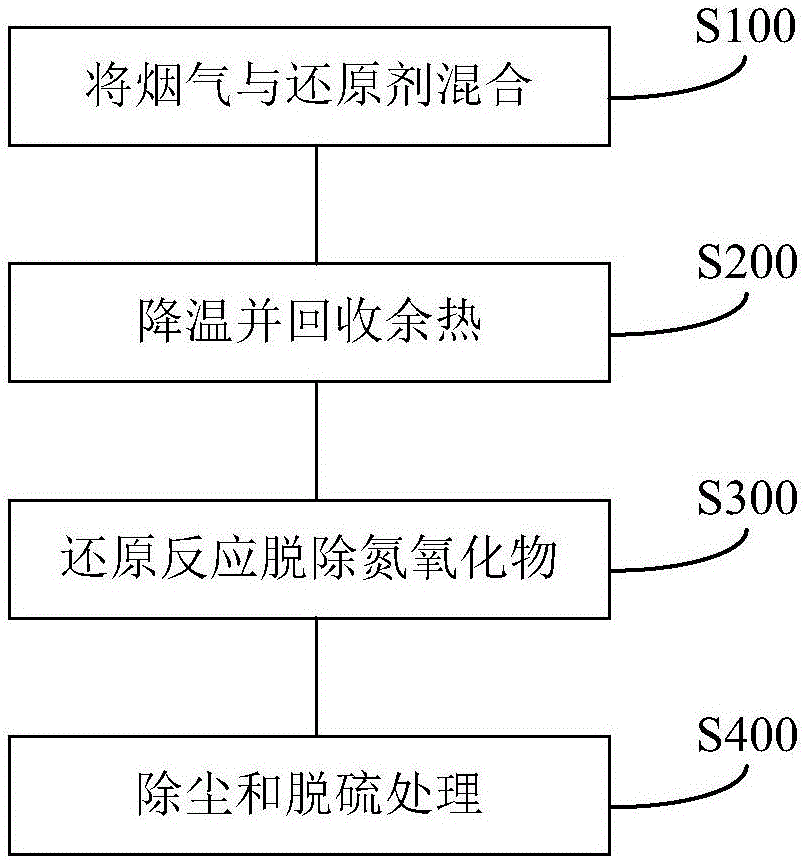
[0120] Anthracite crushed to less than 6mm is sprayed into the furnace of the boiler through the nozzle, mixed with the air sent into the furnace by the blower, and then burned. The temperature in the furnace can reach 1250°C. The high-temperature flue gas produced by combustion passes through the convection tube bundle installed at the flue gas outlet of the furnace to heat and demineralize the water. The flue gas lowered to 950°C enters the flue connected to the heat storage denitrification system, and the atomized reducing agent nozzle installed in it sprays ammonia water droplets, and the flue gas mixes with it quickly and uniformly before entering the heat storage system. , the temperature drops to 450°C and enters the regenerative denitrification system. Under the action of the denitrification heat storage body, while recovering the waste heat of the flue gas, the nitrogen oxides in the flue gas undergo a reduction reaction with ammonia water, and the nitrogen oxides are r...


PUM


Abstract

The invention discloses a flue gas denitrification system and denitrification method for a particle material industrial boiler. The denitrification system comprises an exhaust pipeline, a heat accumulator, a denitrification heat accumulator, a cyclone separation device, a desulfurization device and a chimney, wherein the exhaust pipeline is connected to a flue gas outlet of the particle material industrial boiler, and a reducer nozzle is arranged on the exhaust pipeline; the heat accumulator is arranged in the exhaust pipeline and is located in the downstream of the reducer nozzle, and the heat accumulator is suitable for pre-recovering waste heat of the flue gas; the denitrification heat accumulator is arranged in the exhaust pipeline and is located at the downstream of the heat accumulator, and the denitrification heat accumulator is suitable for recovering the waste heat of the flue gas and denitrifying the flue gas; the cyclone separation device is connected to a gas outlet of the exhaust pipeline and is suitable for dedusting the flue gas; the desulfurization device is connected to the cyclone separation device and is suitable for removing sulfur oxides in the flue gas; and the chimney is connected to the desulfurization device. By using the denitrification system, a denitrification reaction can be performed on the flue gas without dedusting, so that the denitrification system is simple to operate and high in denitrification efficiency.

Description

technical field [0001] The invention belongs to the field of flue gas denitration, in particular, the invention relates to a flue gas denitrification system and a denitrification method for industrial boilers with granular materials. Background technique [0002] With the rapid development of my country's economy, fossil fuels such as natural gas, oil and coal have been more widely used, making environmental problems increasingly serious, which has caused a series of environmental problems, such as acid rain, ozone layer destruction, greenhouse effect, etc., making us The living environment is becoming more and more severe. my country's coal-based energy structure determines that the emissions of nitrogen oxides and sulfur oxides in our country have always been high. The emission of a large amount of polluting gases has made environmental problems increasingly serious, not only seriously affecting the production and life of our people. , and is not conducive to the sustainabl...

Claims


Application Information

Patent Timeline
IPC IPC(8): B01D53/86B01D53/90B01D53/56
CPCB01D53/8631B01D53/90B01D2258/0283
Inventor 吴道洪宋敏洁钟贵全陈珊王志军
Owner SHENWU TECH GRP CO LTD
Why Eureka
Try Eureka