
Sub-region mixing type denitration system of flue gas

A flue gas and denitrification technology, applied in the field of flue gas denitrification, can solve the problems of poor uniformity of ammonia nitrogen ratio and flow field, insufficient mixing of ammonia gas and flue gas, etc., and achieve reduced concentration deviation, compact structure and reasonable layout Effect

Inactive Publication Date: 2017-05-31
STATE GRID HENAN ELECTRIC POWER ELECTRIC POWER SCI RES INST +2
View PDF7 Cites 0 Cited by
  • Summary
  • Abstract
  • Description
  • Claims
  • Application Information

AI Technical Summary

Problems solved by technology

However, this patent only sprays ammonia at the same height, and with the flow of flue gas, it is easy to cause insufficient mixing of ammonia gas and flue gas in the subsequent flue, and the uniformity of the ammonia-nitrogen ratio and the uniformity of the flow field are poor

Method used


Image

  • Sub-region mixing type denitration system of flue gas
  • Sub-region mixing type denitration system of flue gas
  • Sub-region mixing type denitration system of flue gas

Examples


Embodiment 1

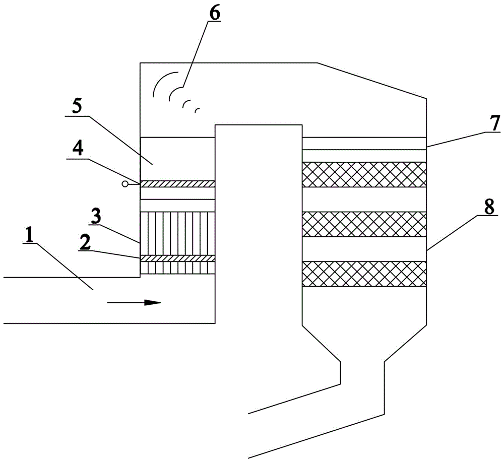
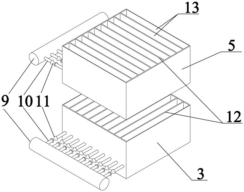
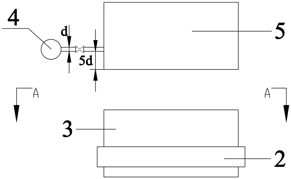
[0027] see Figure 1-4 , a flue gas zoned mixed denitrification system, comprising an SCR inlet flue 1, a first layer of ammonia injection grille 2, a first layer of clapboard partitions 3, and a second layer of ammonia injection grille 4 arranged in sequence along the direction of flue gas advancement , the second layer partition partition 5, the deflector 6, the rectification grid 7 and the SCR reactor 8, the deflector 6 is arranged at the upper corner of the SCR inlet flue 1, and the rectification grid 7 is arranged at The SCR reactor 8 inlet, the first layer partition partition 3 and the second layer partition partition 5 are arranged adjacently in front of the deflector 6 (see figure 1 ), each layer of ammonia injection grid 7 is composed of ammonia supply main pipe 9, several ammonia injection branch pipes 10 and regulating valve 11, ammonia supply main pipe 9 is connected with several ammonia injection branch pipes 10, and the starting position of each ammonia injection...

Embodiment 2

[0030] see Figure 5 , the flue gas partition mixed denitrification system of this embodiment is basically the same as that of Embodiment 1, and the similarities will not be repeated. Some differences are: the first partition partition 3 and the second partition partition 5 are respectively located Plate 6 front and rear.

[0031] Treat a coal-fired power plant with a boiler load of 300MW and a flue gas volume of 1017000Nm by adopting the flue gas partitioned mixed denitrification system of this embodiment 3 / h, ammonia nitrogen ratio 0.80, NO in flue gas x The concentration is 400mg / Nm 3 , so that NO in flue gasx Concentration decreased to 36mg / Nm 3 The denitrification efficiency is 91%, and the ammonia escape concentration is reduced to 3ppm, meeting the requirements of the "ultra-low emission" standard for coal-fired boilers in power plants.

Embodiment 3

[0033] The mixed denitrification system for flue gas partitions in this embodiment is basically the same as that of Embodiment 1, and the similarities will not be repeated. The difference is that the distance between the branch pipe 10 of each layer of ammonia injection and the bottom end of the partition of the corresponding layer is 10 times the diameter d of the ammonia branch pipe 10.

[0034] Treat a coal-fired power plant with a boiler load of 600MW and a flue gas volume of 2,200,000Nm by using the flue gas partitioned mixed denitrification system of this embodiment 3 / h, ammonia nitrogen ratio 0.85, NO in flue gas x The concentration is 500mg / Nm 3 , so that NO in flue gas x Concentration decreased to 44mg / Nm 3 The denitrification efficiency is 91%, and the ammonia escape concentration is reduced to 3ppm, meeting the requirements of the "ultra-low emission" standard for coal-fired boilers in power plants.


PUM


Abstract

The invention belongs to the technical field of flue gas denitration and in particular relates to a sub-region mixing type denitration system of flue gas. The denitration system comprises an SCR (Selective Catalytic Reduction) inlet flue, a first-layer ammonia injection grid, a first-layer separation plate sub-region, a second-layer ammonia injection grid, a second-layer separation plate sub-region and an SCR reactor, wherein each of the first-layer ammonia injection grid and the second-layer ammonia injection grid is composed of an ammonia supplying main pipe, a plurality of ammonia injection branch pipes and an adjusting valve; the first-layer separation plate sub-region and the second-layer separation plate sub-region are uniformly divided into a plurality of flue gas channels through flue separation plates respectively; the direction of the flue separation plates of each layer of the separation plate sub-region is parallel to the direction of the ammonia injection branch pipes of the corresponding layer; each flue gas channel is internally provided with one ammonia injection branch pipe; each ammonia injection branch pipe is provided with a plurality of nozzles with the direction consistent to that of the flue gas. According to the sub-region mixing type denitration system of the flue gas, the uniformity of an ammonia-nitrogen ratio and the uniformly of a flowing field are considered at the same time, and the mixing of ammonia gas and the flue gas adopts a sub-region mixing system; the sub-region mixing type denitration system is compact in structure and reasonable in arrangement, and the mixing effect of the flue gas and the ammonia gas is improved.

Description

technical field [0001] The invention belongs to the technical field of flue gas denitrification, and in particular relates to a flue gas zone mixed denitrification system. Background technique [0002] At present, SCR denitrification technology is widely used in flue gas denitrification technologies at home and abroad due to its high efficiency. With the improvement of environmental protection standards, the requirements for flue gas denitrification efficiency are becoming more and more stringent. In addition to optimizing the catalyst itself, another key factor in improving the SCR denitrification efficiency is the mixing effect of ammonia and flue gas. However, due to space and cost constraints, the mixing time of ammonia and flue gas in SCR denitrification is currently relatively short, and the mixing effect is not good. Therefore, it is of great significance to develop a more suitable and efficient ammonia injection mixing device. [0003] Chinese patent application CN...

Claims


Application Information

Patent Timeline
Patent Type & Authority Applications(China)
IPC IPC(8): B01D53/86B01D53/56
CPCB01D53/8631B01D2251/2062B01D2258/0283
Inventor 毛睿李玲陶云翼赵鑫平胡胜林王贺岑张营帅郭志成徐乃宾李丰朝王留锋
Owner STATE GRID HENAN ELECTRIC POWER ELECTRIC POWER SCI RES INST
Learn More