
High-precision resonant optical voltage sensor and detecting method

An optical voltage, resonant technology, applied in the direction of measuring current/voltage, measuring device, measuring electrical variables, etc., can solve the problem of not completely eliminating temperature error, sensor miniaturization difficulty, error and other problems

Active Publication Date: 2017-05-31
华驰动能(北京)科技有限公司
View PDF5 Cites 11 Cited by
  • Summary
  • Abstract
  • Description
  • Claims
  • Application Information

AI Technical Summary

Problems solved by technology

[0005] Traditional optical voltage sensors based on the Pockels effect usually use longer bismuth germanate (Bi 4 Ge 3 o 12 , BGO) crystal to ensure that the Pockels phase difference it is sensitive to is large enough, but the larger the crystal length, the more difficult it is to miniaturize the sensor; at the same time, as a sensitive device, the BGO crystal’s measurement accuracy is affected by the temperature stability of the crystal, even in some In the improved structure, the improvement effect is also limited, and the addition of optical devices in the improved structure also introduces new error factors, and does not completely eliminate the error caused by temperature
[0006] It can be seen that the existing voltage sensor based on the Pockels effect is difficult to take into account the high precision and miniaturization of the test system due to the restriction of the crystal length
At the same time, the error caused by the temperature of the sensor makes it difficult to guarantee the consistent stability of the voltage measurement performance

Method used


Image

  • High-precision resonant optical voltage sensor and detecting method
  • High-precision resonant optical voltage sensor and detecting method
  • High-precision resonant optical voltage sensor and detecting method

Examples


Embodiment Construction

[0107] The present invention will be described in detail below with reference to the drawings and specific embodiments.

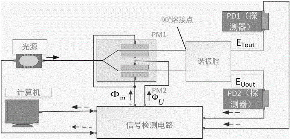
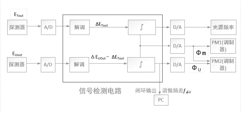
[0108] The high-precision resonant optical voltage sensor of the present invention, through the design of a dual-track resonant optical path, in which two linearly polarized light E U And E T Propagating along the BGO crystal, the temperature field of the two beams at the same time is the same, so the temperature change affects the polarization of the two paths E U And E T The interference caused is also consistent. Synchronously detect two beams of linearly polarized light E in the signal detection circuit U And E T Frequency difference of resonant frequency, linearly polarized light E caused by Pockels effect U The frequency difference information of the resonance frequency change is retained, linearly polarized light E U And E T The rest of the interference in the propagation of the BGO crystal cancels each other out;

[0109] The high-precision resonant optic...


PUM


Abstract

The invention discloses a high-precision resonant optical voltage sensor and a detecting method and belongs to the technical field of optical voltage sensing. The optical voltage sensor comprises a narrow linewidth laser source, a Y waveguide, a BGO crystal, dual detectors and a signal detection circuit which are sequentially connected through polarization maintaining optical fibers. The front light transmitting surface and the rear light transmitting surface of the BGO crystal are coated with films to form a high-definition resonant cavity, and the Pockels effect is improved through multiple times of transmission of light in the resonant cavity. According to the detecting method of the optical voltage sensor, by means of a resonant light path for dual path tracking, the resonant frequency difference of the two beams of light is synchronously detected, interference caused by the temperature change of the two beams of light at the same moment is consistent, the interference variables of the two beams of light in the propagation process are offset, and the improved Pockels effect is reserved. The measuring precision, temperature stability and environment adaptability of the optical voltage sensor are improved, the contradiction of high precision of miniaturization of the voltage sensor is solved, light path devices are reduced, and the structure is simple and reliable.

Description

Technical field [0001] The invention belongs to the technical field of optical voltage sensors, and relates to a high-precision resonant optical voltage sensing and detection method. Background technique [0002] As the power system develops towards high voltage, large capacitance, and digitalization, the power system puts forward higher performance requirements for the power measurement system. As a voltage measurement device, traditional voltage sensors are becoming increasingly unsuitable for the development of power systems due to their inherent defects, which promotes the emergence and development of optical voltage sensors. [0003] The optical voltage sensor is a voltage measurement device that senses the voltage information to be measured by the change of the optical signal. The optical voltage sensor has been extensively researched and developed rapidly due to its small size, good insulation, safety and reliability and a series of advantages. [0004] As a high-voltage meas...

Claims


Application Information

Patent Timeline
IPC IPC(8): G01R19/32
CPCG01R19/32
Inventor 李慧邓炜刘黎映冯丽爽张春熹
Owner 华驰动能(北京)科技有限公司
Learn More