
Urinary bladder pressure monitoring method and system based on optical fibers

A bladder and pressure technology, applied in the directions of diagnostic recording/measurement, medical science, urinary function evaluation, etc., can solve the problems of low measurement accuracy, lack of real-time monitoring of bladder pressure, expensive medical and equipment costs, etc., so as to reduce the detection cost. Effect

Inactive Publication Date: 2017-06-13
CHONGQING TECH & BUSINESS UNIV
View PDF6 Cites 2 Cited by
  • Summary
  • Abstract
  • Description
  • Claims
  • Application Information

AI Technical Summary

Problems solved by technology

Although this method is simple, practical and low in cost, and the measured data can truly reflect the pressure of the bladder, the disadvantage of this method is also obvious, that is, it is necessary to inject physiological saline into the patient's bladder for each measurement, and repeated operations It will bring physical pain to the patient. Inserting the pressure measurement catheter is an invasive operation with a high risk of infection. The entire pressure measurement process is complicated to operate and the nursing workload is heavy. Human factors during the operation can easily affect the measurement results
In addition, bladder pressure can also be measured by urodynamic instrument, but although this method is simple to operate, the cost of medical treatment and equipment is expensive, and it is not widely used.
Therefore, the existing methods of cystometry have obvious shortcomings, and the accuracy of measurement is not high. More importantly, the lack of real-time monitoring of bladder pressure will delay and miss good opportunities for treatment to a certain extent.

Method used


Image

  • Urinary bladder pressure monitoring method and system based on optical fibers
  • Urinary bladder pressure monitoring method and system based on optical fibers
  • Urinary bladder pressure monitoring method and system based on optical fibers

Examples


Embodiment Construction

[0042] The core idea of ​​the present invention is to provide a method and system for monitoring bladder pressure based on optical fiber, which can accurately, conveniently and dynamically monitor the bladder pressure of patients with urinary tract disorders, and can reduce the detection cost.

[0043] The following will clearly and completely describe the technical solutions in the embodiments of the present invention with reference to the accompanying drawings in the embodiments of the present invention. Obviously, the described embodiments are only some, not all, embodiments of the present invention. Based on the embodiments of the present invention, all other embodiments obtained by persons of ordinary skill in the art without making creative efforts belong to the protection scope of the present invention.

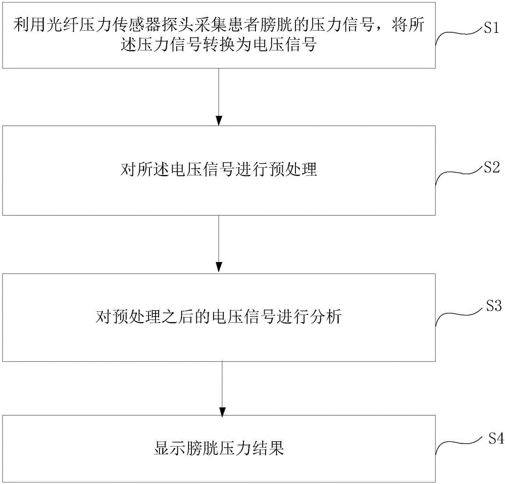
[0044] The first method of monitoring bladder pressure based on optical fiber provided by the embodiment of the present application is as follows: figure 1 as shown, ...


PUM


Abstract

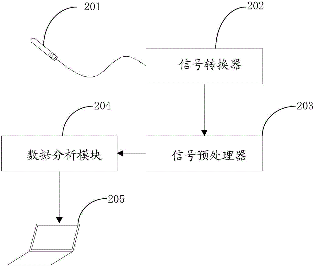
The invention discloses a urinary bladder pressure monitoring method and system based on optical fibers. The method comprises the steps as follows: a pressure signal of the urinary bladder of a patient is acquired by an optical fiber pressure sensor probe and converted into a voltage signal; the voltage signal is preprocessed; the preprocessed voltage signal is analyzed; a urinary bladder pressure result is displayed. The system comprises the optical fiber pressure sensor probe for acquiring the pressure signal of the urinary bladder of the patient, a signal converter for converting the pressure signal into the voltage signal, a signal preprocessor for preprocessing the voltage signal, a data analysis module for analyzing the preprocessed voltage signal and a display module for displaying the urinary bladder pressure result. With the adoption of the method and system, the urinary bladder pressure of the patient suffering from urinary tract dysfunction can be monitored accurately, conveniently and dynamically, and the detection cost can be reduced.

Description

technical field [0001] The invention belongs to the technical field of human health monitoring, in particular to a method and system for monitoring bladder pressure based on optical fiber. Background technique [0002] The lower urinary tract disorder caused by spinal injury can cause complications such as urinary incontinence, urinary retention, urinary tract infection and urinary reflux, and later lead to chronic renal failure or even death, which is a major problem facing medicine. At present, the more effective and commonly used method for the treatment of patients with lower urinary tract disorder after spinal injury is intermittent catheterization, which needs to be based on bladder pressure. [0003] For the measurement of bladder pressure, it is generally performed by inserting a catheter into the bladder from the urethra, and slowly injecting a certain amount of normal saline into the bladder, and then measuring the pressure when the fluid flows out of the bladder. ...

Claims


Application Information

Patent Timeline
Patent Type & Authority Applications(China)
IPC IPC(8): A61B5/20A61B5/00
Inventor 陈旭东陈志强刘杰刘传文成志伟白云姚行艳李川喻其炳
Owner CHONGQING TECH & BUSINESS UNIV
Learn More