Method for improving gain of microchannel plate

A technology of microchannel plate and dielectric film layer, which is applied in the direction of multiple dynode electrode devices, dynodes, electron multiplier tubes, etc., to achieve the effect of improving the yield rate

Active Publication Date: 2017-06-13
NORTH NIGHT VISION TECH
View PDF7 Cites 11 Cited by
  • Summary
  • Abstract
  • Description
  • Claims
  • Application Information

AI Technical Summary

Problems solved by technology

Therefore, the film layer deposited by this technology is available at any position on the MCP, not only in the channel, but also on the input and output surfaces, and the thickness is the same, so the atomic layer deposition technology cannot be selectively deposited on the MCP. Coating on the input or output side of the

Method used


Image

  • Method for improving gain of microchannel plate
  • Method for improving gain of microchannel plate
  • Method for improving gain of microchannel plate

Examples


Embodiment 1

[0024] Put the MCP with a diameter of Φ25mm and a channel diameter of 6 μm into the MCP coating fixture, and put the coating fixture together with the MCP on the workpiece turntable of the coating machine. The coating machine is the ARES710 coating machine of LEYBOLD OPTICS Company.

[0025] Put a certain amount of silica particles in the crucible of the coating machine. The manufacturer of silica is UMICORE Company, the brand is 0481269, the particle size is 0.2-0.7mm, and the purity is 99.99%.

[0026] Close the coater door. Set the parameters of the coating machine as follows: start the vacuum pumping system of the coating machine. When the vacuum degree of the coating machine reaches 4×10 -5 After lifting, start to heat the turntable of the coating machine, the temperature is set to 120° C., the heating time is 25 minutes, and the holding time is 15 minutes.

[0027] After the heating is over, start the coating program. The coating procedure is basically the same as t...


PUM


Abstract

The invention discloses a method for improving gain of a microchannnel plate. A dielectric film layer is evaporated on the input end of the microchannel plate by means of a vacuum evaporating method, thereby covering a metal input electrode. The dielectric film layer covers an input electrode at a chananel inlet of the microchannel plate and furthermore covers an input electrode on the input-end surface of the microchannel plate. The dielectric film layer is made of silicon dioxide (SiO2), titanium dioxide (TiO2) and aluminum oxide (Al203). After the method of the invention is utilized, the gain of the microchannel plate is improved by more than one time without characteristic change of the original microchannel plate, such as parameters of plate resistance, dark current, resolution, etc. The method settles a problem of image intensifier discard caused by incapability of satisfying the requirement by partial MCPs in the manufacture process of the image intensifier, and furthermore improves yield rate of super-second-generation image intensifiers in manufacture.

Description

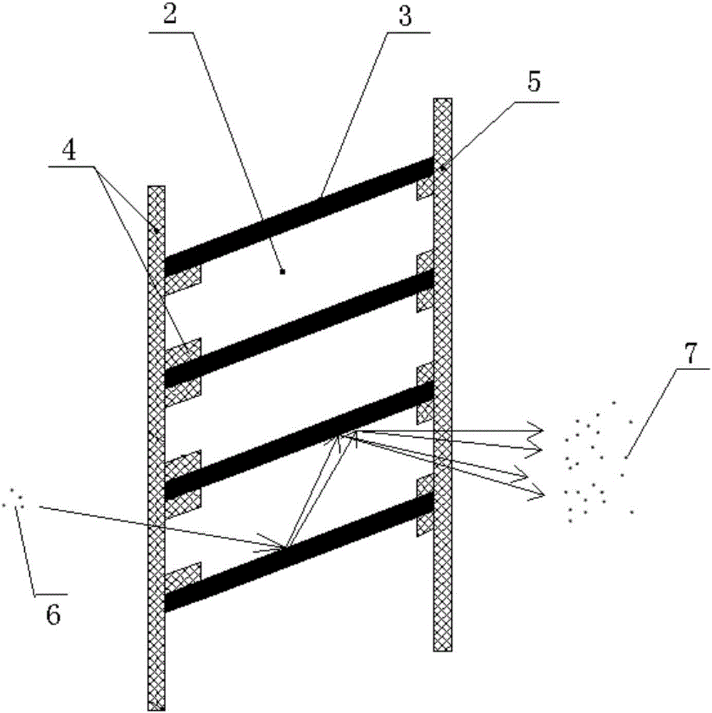
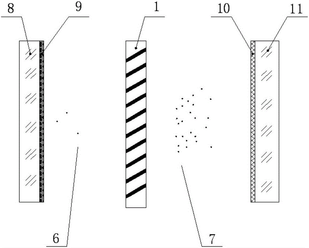
technical field [0001] The invention belongs to the technical field of low-light image intensifiers, and in particular relates to a method for increasing the gain of a micro-channel plate. Background technique [0002] Micro Channel Plate (MCP) is a porous two-dimensional fiber array composed of millions of hollow fiber tubes, see figure 1 and figure 2 . figure 1 is the structure diagram of MCP, figure 2 It is a partially enlarged schematic diagram of MCP. Each hollow fiber tube of the MCP is an independent electron multiplication channel 2 . The input end and the output end of the channel 2 are respectively fabricated with an input electrode 4 and an output electrode 5, and the surface of the inner wall 3 of each channel has secondary electron emission characteristics. The material of the input and output electrodes is nickel-chromium alloy (Ni-Cr). The electrodes function to apply voltage and supply current to the input and output terminals of the MCP. When the MC...

Claims


Application Information

Patent Timeline
Patent Type & Authority Applications(China)
IPC IPC(8): H01J9/12H01J43/24
CPCH01J9/125H01J43/246
Inventor 李晓峰张彦云张俊李廷涛许有毅余家粱常乐瞿利平
Owner NORTH NIGHT VISION TECH
Why Eureka
Try Eureka