Low-resistance silicon on insulator-lateral insulated gate bipolar transistor (SOI-LIGBT) device capable of preventing snapback effect and manufacturing method thereof

A negative resistance effect and device technology, applied in the field of SOI-LIGBT devices and their manufacturing, can solve problems affecting device performance, etc., and achieve the effects of reducing device area, increasing vertical breakdown voltage, and low conduction loss

Inactive Publication Date: 2017-06-20
UNIV OF ELECTRONIC SCI & TECH OF CHINA +1
View PDF4 Cites 2 Cited by
  • Summary
  • Abstract
  • Description
  • Claims
  • Application Information

AI Technical Summary

Problems solved by technology

A technical solution to this problem is the reverse conduction insulated gate bipolar transistor (RC-IGBT), but this solution will introduce a new problem to the IGBT, that is, the negative resistance (Snapback) effect, which will affect the performance of the device

Method used


Image

  • Low-resistance silicon on insulator-lateral insulated gate bipolar transistor (SOI-LIGBT) device capable of preventing snapback effect and manufacturing method thereof
  • Low-resistance silicon on insulator-lateral insulated gate bipolar transistor (SOI-LIGBT) device capable of preventing snapback effect and manufacturing method thereof
  • Low-resistance silicon on insulator-lateral insulated gate bipolar transistor (SOI-LIGBT) device capable of preventing snapback effect and manufacturing method thereof

Examples


Embodiment 1

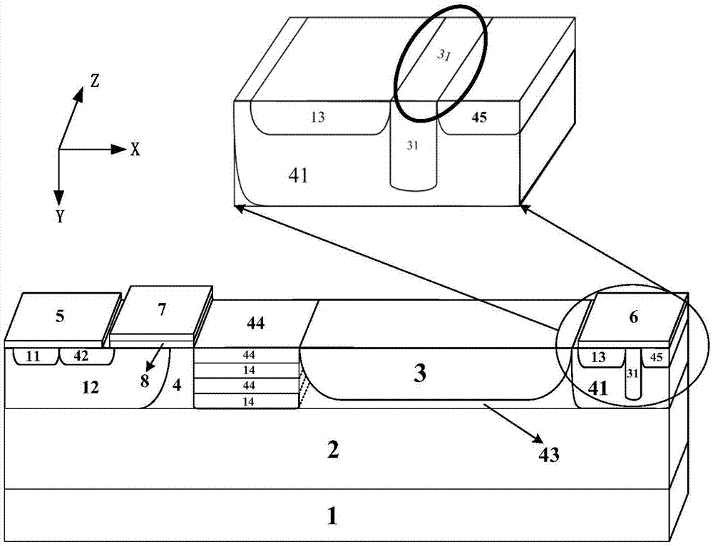
[0058] Such as figure 2 as shown, figure 2 It is a schematic diagram of the SOI-LIGBT device structure with low resistance and can suppress the negative resistance effect of this embodiment; its cell structure includes a substrate 1, a buried oxide layer 2 on the upper surface of the substrate 1, and a thickness above the buried oxide layer 2 The dielectric layer 3, the thick silicon layer drift region 4 on the left side of the thick dielectric layer 3, the P well region 12 at the left end inside the thick silicon layer drift region 4, and the mutually independent P-type heavily doped emitters arranged inside the P well region 12 The pole region 11 and the first N-type heavily doped region 42, the N-type buffer region 41 disposed at the right end of the thick dielectric layer 3 along the longitudinal direction, the P-type heavily doped collector region 13 at the left end inside the N-type buffer region 41, The second N-type heavily doped region 45 at the right end of the N-...

Embodiment 2

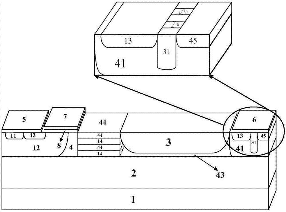
[0075] Such as image 3 As shown, this embodiment is basically the same as Embodiment 1, the difference is that: the collector dielectric barrier layer 31 in this embodiment includes a plurality of sub-barrier layers separated by N-type buffer regions 41 in the Z direction, adjacent sub-barrier layers The distance between the barrier layers in the Z direction is a.

Embodiment 3

[0077] Such as Figure 4 As shown, this embodiment is basically the same as Embodiment 1, with the difference that: in this embodiment, the N strips 44 and the P strips 14 are not in contact with the upper surface of the buried oxide layer 2 .


PUM


Abstract

The invention provides a low-resistance silicon on insulator-lateral insulated gate bipolar transistor (SOI-LIGBT) device capable of preventing a snapback effect and a manufacturing method thereof. A cell structure of the low-resistance SOI-LIGBT comprises a substrate, a buried oxide layer, a thick dielectric layer, a thick silicon layer drift region, a P well region, a P-type heavily-doped emitter region, a first N-type heavily-doped region, an N-type buffer region, a P-type heavily-doped collector region, a second N-type heavily-doped region, a collector dielectric blocking layer, a collector contact electrode, an ultrathin top-layer silicon drift region, an emitter contact electrode, a gate oxide layer, a poly-silicon gate, P strips and N strips, wherein the N strips are alternatively arranged in the thick silicon layer drift region in longitudinal directions of the P strips. The electric field of the buried layer is improved by employing the ultrathin top layer silicon drift region to increase the longitudinal breakdown voltage of an SOI device; the specific on resistance of the device is reduced by employing the thick silicon layer drift region; and for the ultrathin top layer silicon drift region and the thick silicon layer drift region, lateral linearity variable doping is used for adjusting surface electric field distribution, so that the specific on resistance is greatly reduced as well as high breakdown voltage of the device is greatly maintained.

Description

technical field [0001] The invention belongs to the technical field of semiconductor power devices, and in particular relates to an SOI-LIGBT device with low resistance and capable of suppressing negative resistance effect and a manufacturing method thereof. Background technique [0002] Compared with conventional bulk silicon technology, SOI technology has the advantages of high speed, low power consumption, high integration, small parasitic effect, good isolation characteristics, small latch-up effect and strong radiation resistance, which makes the reliability and anti-software of integrated circuits The ability to make mistakes has been greatly improved, and it is gradually becoming the mainstream technology for manufacturing integrated circuits with high speed, low power consumption, high integration and high reliability. [0003] Lateral Insulated Gate Bipolar Transistor (LIGBT: Lateral Insulated Gate Bipolar Transistor) has the advantages of high input impedance, volt...

Claims


Application Information

Patent Timeline
IPC IPC(8): H01L29/739H01L29/06H01L29/36H01L21/331
CPCH01L29/7393H01L29/0611H01L29/0684H01L29/36H01L29/66325
Inventor 乔明詹珍雅章文通何逸涛肖倩倩余洋王正康张波
Owner UNIV OF ELECTRONIC SCI & TECH OF CHINA
Why Eureka
Try Eureka