Flexible welding system capable of horizontally rotating and shifting car models

A technology of horizontal rotation and welding system, applied in welding equipment, welding equipment, auxiliary welding equipment, etc., can solve the problems of low welding efficiency, difficult automatic robot welding, and large investment.

Pending Publication Date: 2017-06-23
GUANGZHOU RISONG HOKUTO AUTOMOTIVE EQUIP CO LTD
8 Cites 0 Cited by

AI-Extracted Technical Summary

Problems solved by technology

[0003] However, in the existing automatic welding system, there are large investment, single application variety, low efficiency of robots in the automatic welding system, and long flexible switching time of the production line, resulting in low welding efficiency. There are many unstable factors
[0004] At present, flexible welding and welding production lines at home and abroad are basically used in large-scale vehicle production lines to meet the flexible production of two or three models. The main method is to dynamically identify the models and then replace the corresponding tooling to realize the positioning welding of different models. It is a large-scale complete vehicle with a relatively large volume, and generally adopts an assembly line single-line production mode, which takes up a relatively large space
For the weldin...

Abstract

The invention discloses a flexible welding system capable of horizontally rotating and shifting car models. The flexible welding system comprises one or more welding robots, wherein a welding work table for allowing work pieces to be placed is arranged on one sides of the welding robots; a guard fence is arranged around the welding robots and the welding work table, and a manual piece taking and placing opening is formed in the guard fence, manual guardrails, a safety light curtain, a foot light curtain and an operation panel are arranged at the manual piece taking and placing opening; a robot control cabinet and a welding work table control cabinet are arranged on the outer side of the guard fence; the welding robots are connected with the robot control cabinet; the welding work table is connected with the welding work table control cabinet; and a welding clamp set comprises a horizontal rotating clamp set and a fixing clamp set. According to the flexible welding system disclosed by the invention, the applying deficiency of intelligent robots in the field of manufacturing of automobiles is sufficiently considered; the work table capable of horizontally rotating and shifting the car models is allocated for the robots, so that under the premise that the reforming degree of a robot welding system is minimum, multi-car-model flexible production is realized; and the flexible welding system is low in occupied area, high in production efficiency, high in automation degree and good in compatibility, can be matched with other automated production equipment for use, and can be greatly applied in the layout situation with large horizontal space.

Application Domain

Welding/cutting auxillary devicesAuxillary welding devices +4

Technology Topic

Robot controlSurface plate +7

Image

  • Flexible welding system capable of horizontally rotating and shifting car models
  • Flexible welding system capable of horizontally rotating and shifting car models

Examples

  • Experimental program(1)

Example Embodiment

[0018] The technical solutions in the embodiments of the present invention will be clearly and completely described below in conjunction with the accompanying drawings.
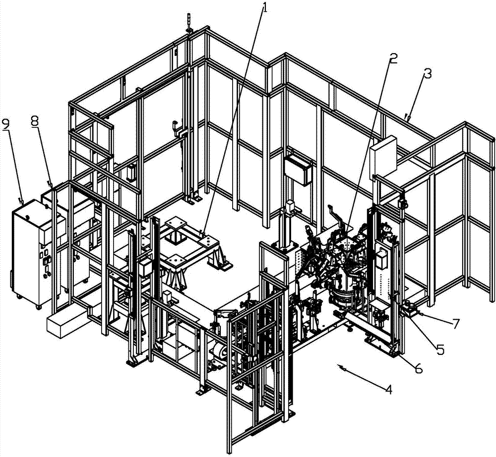
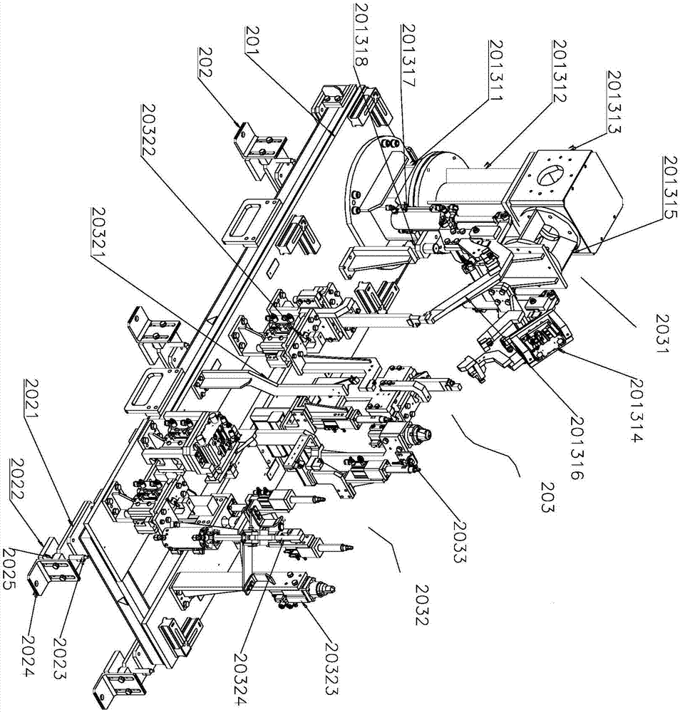
[0019] Such as figure 1 , 2 As shown, the horizontally rotating vehicle switching flexible welding system includes a welding robot (not shown in the figure). The welding robot is installed and fixed by the robot stand 1, and a welding table 2 for placing the workpiece is provided on one side of the welding robot. There is a safety fence 3 around the welding robot and welding workbench 2, the corresponding safety fence 3 on the other side of the welding workbench 2 is equipped with a manual pick-and-place part 4, and the manual pick-and-place part 4 is equipped with a manual guardrail (not shown in the figure) Out), safety grating 5, foot grating 6, operation panel 7. The outer side of the safety fence 3 is provided with a robot control cabinet 8 and a welding workbench control cabinet 9; the welding robot is connected with the robot control cabinet 8; the welding workbench 2 is connected with the welding workbench control cabinet 9.
[0020] In order to improve production efficiency, each welding system can be equipped with multiple welding robots for simultaneous welding operations.
[0021] The welding workbench 2 includes a rectangular base 201, which is installed on the ground through an adjusting device 202; a welding fixture group 203 is installed above the rectangular base 201, and the welding fixture group 203 includes a horizontal rotating fixture group 2031 installed at one end of the rectangular base 201 , A fixed clamp set 2032 installed on the other end of the rectangular base 201.
[0022] The horizontal rotating fixture group 2031 includes a circular base 201311 installed on the upper surface of the rectangular base 201, the circular base 201311 is provided with a servo motor (not shown in the figure), and a coaxially arranged support is connected above the circular base 201311 Column 201312, the support column 201312 is driven by a servo motor to rotate relative to the circular base 201311. The top of the support column 201312 is equipped with a multi-faceted mounting plate 201313. The multi-faceted mounting plate 201313 includes 4 sides. A total of 4 sets of switching fixtures 201314 can be installed. Realize the clamping of four different workpieces. The multi-sided mounting board 201313 can be designed into any number of surfaces, and each surface can be the same or different in size to install different switching fixtures 201314.
[0023] The switching fixture 201314 includes a flange connecting plate 201315 connected to a multi-faceted mounting plate 201313, a workpiece clamping jaw 201316 is installed on the flange connecting plate 201315, and the workpiece clamping jaw 201316 is driven by a jaw cylinder 201317; the horizontal rotating fixture group 2031 An angle detection switch 201318 is also provided, and the angle detection switch 201318 is installed on the support column 201312.
[0024] The fixed clamp set 2032 includes a fixed support 20321, a movable support 20322, a movable positioning pin 20323, and a movable clamping jaw 20324. The fixed support 20321 is installed on a rectangular base 201 through a fixed support rod (not shown in the figure) On the surface, the movable support 20322, the movable positioning pin 20323, and the movable clamping jaw 20324 are driven by an air cylinder (not shown in the figure).
[0025] The adjusting device 202 includes an adjusting plate 2021 fixedly connected to the rectangular base 201, and a fixed plate 2022 fixedly connected to the ground. The fixed plate 2022 and the adjusting plate 2021 are respectively screwed on the adjustable-length bolts 2023, and the adjusting plate 2021 is adjustable through The long bolt 2023 is supported above the fixing plate 2022. One side of the fixing plate 2022 is provided with a lateral positioning plate 2024 bent at a right angle. The lateral positioning plate 2024 is equipped with a pressure block for lateral positioning and pressing of the adjusting plate 2021. 2025.
[0026] A plurality of vehicle type detection switches 2033 are installed on the welding fixture group 203, and the vehicle type detection switches 2033 are installed in different positions to perform detection of different vehicle types.
[0027] The described embodiments are only a part of the embodiments of the present invention, rather than all the embodiments. Based on the embodiments of the present invention, all other embodiments obtained by those of ordinary skill in the art without creative work shall fall within the protection scope of the present invention.

PUM

no PUM

Description & Claims & Application Information

We can also present the details of the Description, Claims and Application information to help users get a comprehensive understanding of the technical details of the patent, such as background art, summary of invention, brief description of drawings, description of embodiments, and other original content. On the other hand, users can also determine the specific scope of protection of the technology through the list of claims; as well as understand the changes in the life cycle of the technology with the presentation of the patent timeline. Login to view more.
Why Eureka
Try Eureka