Pressure sensitive layer applied to piezoresistive pressure sensor and piezoresistive pressure sensor

A pressure sensor and sensitive layer technology, applied in the direction of fluid pressure measurement, instrument, and measurement force by changing ohmic resistance, can solve the problems of high cost and low sensitivity, and achieve high sensitivity, good flexibility, and easy miniaturization. Effect

Pending Publication Date: 2017-07-07
SHENZHEN GRADUATE SCHOOL TSINGHUA UNIV
View PDF9 Cites 38 Cited by
  • Summary
  • Abstract
  • Description
  • Claims
  • Application Information

AI Technical Summary

Problems solved by technology

But at present, piezoresistive pressure sensors still have some shortcomings, such as low sensitivity and high cost.

Method used


Image

  • Pressure sensitive layer applied to piezoresistive pressure sensor and piezoresistive pressure sensor
  • Pressure sensitive layer applied to piezoresistive pressure sensor and piezoresistive pressure sensor
  • Pressure sensitive layer applied to piezoresistive pressure sensor and piezoresistive pressure sensor

Examples


Embodiment 1

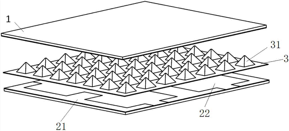
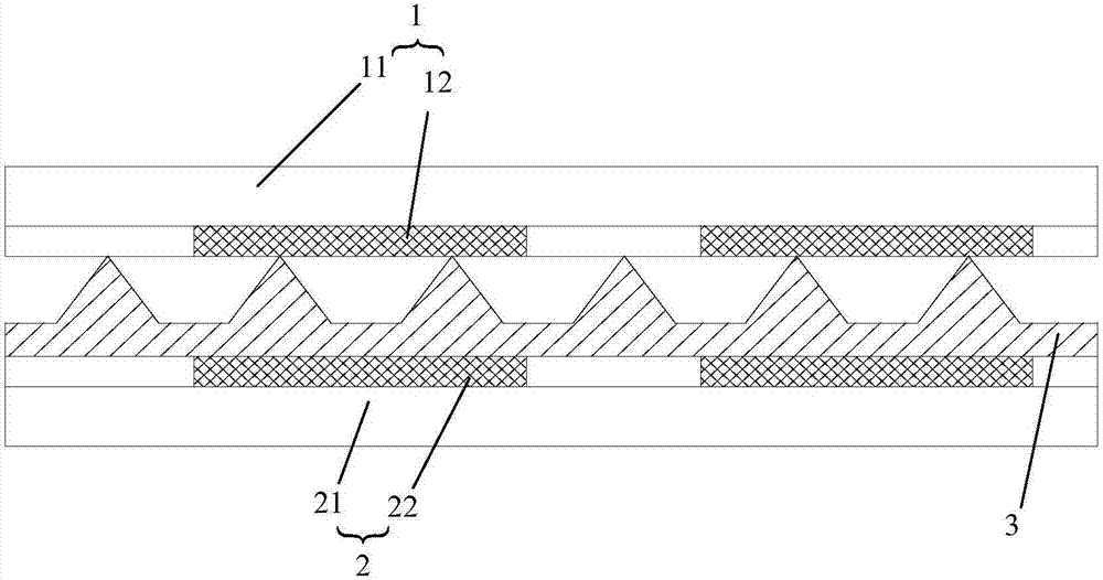
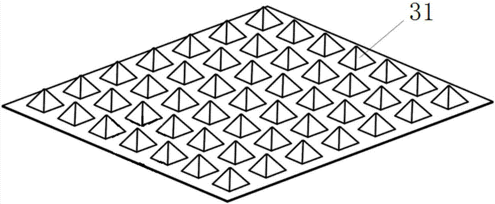
[0035] Such as figure 1 with figure 2 As shown, the piezoresistive pressure sensor includes a first electrode plate 1, a second electrode plate 2 and a pressure sensitive layer 3 sandwiched between the two. The pressure sensitive layer has one layer, and at least one microstructure 31 in its microstructure array is connected to the The electrodes of the first electrode plate 1 are in contact, and the first electrode plate 1 , the pressure sensitive layer 3 and the second electrode plate 2 are bonded to each other. Wherein, the first electrode plate 1 comprises the first substrate film 11 and the first electrode 12, the second electrode plate 2 comprises the second substrate film 21 and the second electrode 22, the first electrode 12 and the second electrode 22 can adopt Certain shapes of ITO (indium tin oxide), silver nanowires. Conductive film materials such as graphene, polymer materials such as PET and PMMA can be used for the first substrate film 11 and the second subst...

Embodiment 2

[0046] In this example, a patterned silver nanowire film is selected as the first electrode and the second electrode to extract electrical signals. The main difference between this example and example 1 is that the pressure sensitive layer has two layers. Such as Image 6 As shown, the fabrication process of the piezoresistive pressure sensor is as follows:

[0047] S1, utilizing silicon wet etching process (potassium hydroxide solution can be used, the proportion is: KOH: 70g, H 2 O: 190mL, isopropanol (IPA): 40mL; magnetic stirring in a water bath at 80°C) to make a microstructure silicon mold with a pitch of 50μm and a microstructure height of 20μm and silanize the surface (in this example, use 1H, 1H, 2H, 2H - Perfluorodecyltrichlorosilane, treated at 120°C for 3h) to obtain a hydrophobic surface;

[0048] S2. Coating liquid polyimide on the microstructured silicon mold, curing and forming at a high temperature of 400°C;

[0049] S3. Using a laser 6 with a power of 5.5W...


PUM

PropertyMeasurementUnit
thicknessaaaaaaaaaa
thicknessaaaaaaaaaa
porosityaaaaaaaaaa

Abstract

The invention discloses a pressure sensitive layer applied to a piezoresistive pressure sensor and the piezoresistive pressure sensor. The pressure sensitive layer comprises a graphene material and a polymer elastomer. The graphene material is loose and porous and has a microstructural array. The polymer elastomer coats the graphene material and penetrates into each hole of the graphene material. The piezoresistive pressure sensor comprises a first electrode plate, a second electrode plate and at least one pressure sensitive layer disposed between the first electrode plate and the second electrode plate, wherein the first electrode plate and the second electrode plate are bonded to each other. The microstructure in the microstructural array contacts electrodes in the first electrode plate and/or the second electrode plate. The piezoresistive pressure sensor provided by the invention can transform the external pressure magnitude into the resistance value of the sensor, senses the change of the external pressure through the change of an electrical signal, and has the advantages of high sensitivity, low cost, high flexibility, easy processing, easy array and miniaturization and the like.

Description

technical field [0001] The invention relates to the technical field of pressure sensors, in particular to a pressure sensitive layer for a piezoresistive pressure sensor and a piezoresistive pressure sensor. Background technique [0002] With the development of microcomputer and Internet of Things technology and the implementation of Industry 4.0, wearable devices, as the interface of the Internet of Things to sense life signals, are getting more and more attention and development, which can complete the collection and detection of various vital signs signals with analysis and display on the terminal device. In order to ensure the flexibility, comfort and portability of wearable devices, flexible sensors and electronic skin have become research hotspots for wearable devices. High-sensitivity flexible pressure sensors can collect various signs of life, such as breathing, heart rate, and pulse, and have attracted much attention in this research. At the same time, the high-se...

Claims


Application Information

Patent Timeline
Patent Type & Authority Applications(China)
IPC IPC(8): G01L1/22G01L9/04
CPCG01L1/22G01L9/04
Inventor 张旻王旭东刘易鑫梁家铭吴一川王晓浩
Owner SHENZHEN GRADUATE SCHOOL TSINGHUA UNIV
Why Eureka
Try Eureka