Supercharge Your Innovation With Domain-Expert AI Agents!

Long-optical-path air chamber with stable encapsulation structure

A packaging structure, long optical path technology, applied in the field of long optical path gas chamber, can solve the problems of change, easy deformation, unstable optical structure, etc.

Active Publication Date: 2017-07-18
JIANGSU XUHAI OPTO ELECTRONIC TECH CO LTD
View PDF8 Cites 6 Cited by
  • Summary
  • Abstract
  • Description
  • Claims
  • Application Information

AI Technical Summary

Problems solved by technology

In order to meet the needs of processing flexibility, the base and the packaging rod are usually made of metal, and its thermal expansion coefficient often does not match the thermal expansion coefficient of the optical material of the optical mirror (201, 202), resulting in thermal instability of the optical system; in addition, the base Under the action of external force or due to the residual stress in the process of processing, the metal material of the packaging rod is easy to deform over time, which also causes changes in the optical path
can be seen, figure 2 Although the package structure shown is relatively simple, the output optical power is easily affected by temperature, stress, and mechanical vibration, and the optical structure is unstable.

Method used


Image

  • Long-optical-path air chamber with stable encapsulation structure
  • Long-optical-path air chamber with stable encapsulation structure
  • Long-optical-path air chamber with stable encapsulation structure

Examples


Embodiment 1

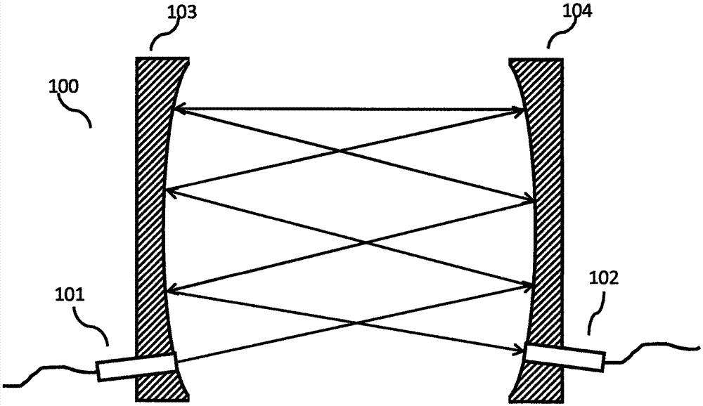
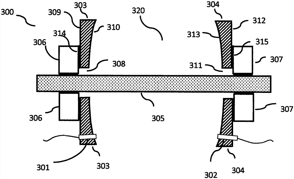
[0051] Such as Image 6 As shown, the long optical path gas chamber (600) provided by the present invention comprises:

[0052] 1. An input port (601) for inputting a light beam;

[0053] 2. An output port (602) for outputting light beams;

[0054] 3. A first concave reflector (603), having a first central hole, a first adhesive surface, and a first reflective surface, the first reflective surface having a first focal length f1;

[0055] 4. A second concave reflector (604), having a second central hole, a second bonding surface, and a second reflective surface, the second reflective surface having a second focal length f2;

[0056] 5. A package post (605) having an outer diameter R and a length L;

[0057] 6. A first collar (606) having a first inner diameter R1 and a third bonding surface;

[0058] 7. A second collar (607) having a second inner diameter R2 and a fourth bonding surface.

[0059] The first and second reflective surfaces of the first and second concave mirr...

Embodiment 2

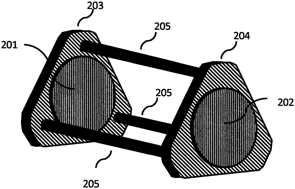
[0070] Such as Figure 7 As shown, the second embodiment of the long optical path gas cell (700) provided by the present invention has an optical and mechanical structure similar to that of embodiment 1, and optically adopts the Herriott gas cell configuration as well. The difference is that the outer package (709) is an open structure open to the ambient atmosphere, and no air inlet and outlet are needed, and the three columnar connecting rods (708) in the outer package connect the outer package The left and right parts are connected, Figure 7 Only two columnar connecting rods are drawn in .

[0071] The input end (701) is still an optical fiber collimator with a pigtail, and the laser beam collimated at the input end is fed into the reflection cavity through two total internal reflections of the parallelogram prism (707), and the first concave reflector ( 703) no longer needs to fix the small hole of the fiber collimator, and the fiber collimator and the parallelogram pri...


PUM


Abstract

The invention provides a long-optical-path air chamber with a stable encapsulation structure. By adopting an encapsulation column, a loop and a concave reflective mirror with a central hole, optical and mechanical elements are closely laminated or sheathed, the optical path of the air chamber can be ensured to have stability to temperature and mechanical stress change while the flexible adjustment capability of the optical path of the air chamber is realized. The invention further provides a buffer ring with certain elasticity, the optical element of a reflective cavity is buffered and separated from an outer encapsulation body, and the optical stability of the air chamber is further enhanced.

Description

technical field [0001] The invention relates to a long optical path gas chamber for gas sensing, in particular to a long optical path gas chamber with a stable packaging structure, which is easy to adjust the optical path and has high temperature and mechanical stability. Background technique [0002] The detection of dangerous gases such as gas and carbon monoxide is of great significance for the safety protection of dangerous workplaces such as coal mines and oil and gas fields. It is of great significance to detect early release of dangerous gases and prevent problems before they happen. At this stage, tunable laser absorption spectroscopy technology has been widely used in the field of gas sensing. This technology uses the characteristic absorption peaks of gas, carbon monoxide and other dangerous gas molecules in the near-infrared band over-frequency and combined frequency bands, and uses adjustable laser scanning in this band to obtain the intensity of the characterist...

Claims


Application Information

Patent Timeline
IPC IPC(8): G01N21/01
CPCG01N21/01
Inventor 陈波何光芝左惟涵温俊华
Owner JIANGSU XUHAI OPTO ELECTRONIC TECH CO LTD
Features
  • R&D
  • Intellectual Property
  • Life Sciences
  • Materials
  • Tech Scout
  • Unparalleled Data Quality
  • Higher Quality Content
  • 60% Fewer Hallucinations
Learn More