
Pulse energy injection type wireless electric energy transmission device

A technology of wireless energy transmission and pulse energy, applied in the direction of circuit devices, electrical components, etc., can solve the problems of reducing resonance quality factor, low transmission power level, increasing coil loss, etc., to improve quality factor, high resonance quality factor, reduce The Effect of Switching Losses

Inactive Publication Date: 2017-07-21
BEIJING INSTITUTE OF TECHNOLOGYGY
View PDF6 Cites 6 Cited by
  • Summary
  • Abstract
  • Description
  • Claims
  • Application Information

AI Technical Summary

Problems solved by technology

[0005] Although the above-mentioned patents reduce the switching loss to a certain extent or realize constant energy input, the implementation circuit of Patent 1 is costly and too complicated. Although the circuit structure of Patent 2 is simple, the switching tube is subjected to high voltage during the energy injection process. Therefore, the transmission power level is low. In addition, the resonant circuit of patent 2 includes a switch tube. Since the on-state resistance of the switch tube is much larger than the parasitic resistance of the resonant capacitor and resonant inductor, this reduces the resonance quality factor and increases the coil loss.

Method used


Image

  • Pulse energy injection type wireless electric energy transmission device
  • Pulse energy injection type wireless electric energy transmission device
  • Pulse energy injection type wireless electric energy transmission device

Examples


Embodiment

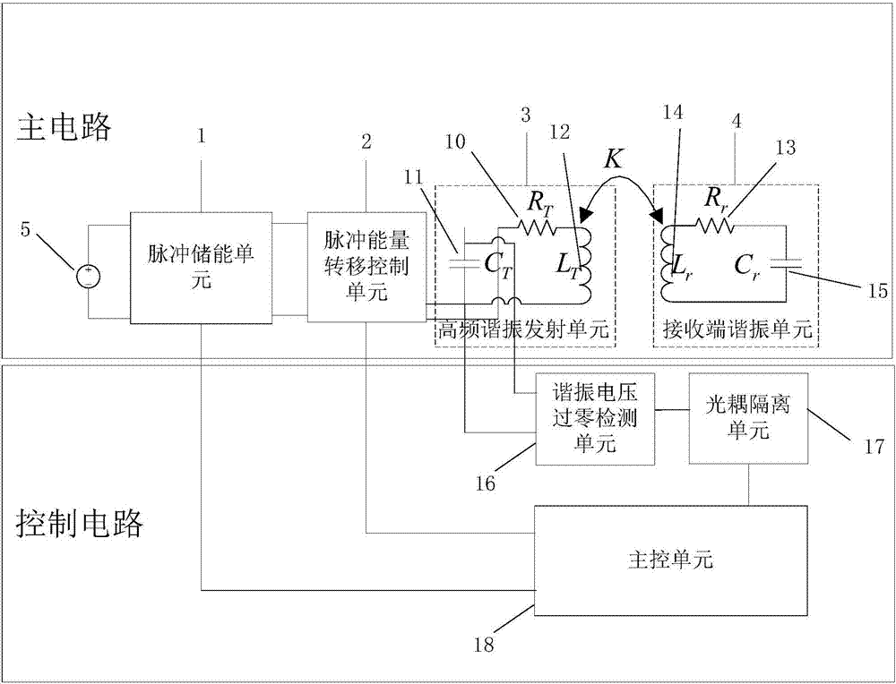
[0039] The basic structural block diagram of the present invention is as figure 1 As shown, it consists of two parts, the main circuit and the control circuit. The main circuit includes five sub-units: pulse energy storage unit 1, pulse energy transfer control unit 2, high-frequency resonance transmitting unit 3, receiving end resonance unit 4, and DC power supply 5. The control circuit includes three subunits: a resonant voltage zero-crossing detection unit 16 , an optocoupler isolation unit 17 , and a main control unit 18 .

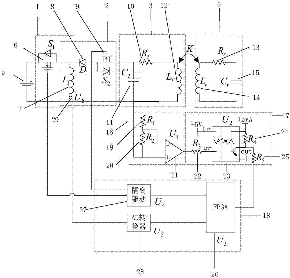
[0040] The pulse energy storage unit 1 includes a switch tube S 1 6. Main inductance L 1 7. Switch tube S 1 6 is connected to the DC power supply 5 and the main inductor L 1 Between 7; switch tube S 1 The drain of 6 is connected to the positive pole of DC power supply 5, and the switch tube S 1 The source of 6 is connected to the main inductor L 1 7 and diode D 1 8 cathodes.

[0041] The pulse energy transfer control unit 2 includes a main induc...


PUM


Abstract

The invention discloses a pulse energy injection type wireless electric energy transmission device. The device comprises a main circuit and a control circuit. The main circuit comprises a pulse energy storage unit, a pulse energy transferring control unit, a high frequency resonance emission unit and a receiving end resonance unit. The control circuit comprises a resonance voltage zero-cross detection unit, an optical coupling isolation unit and a main control unit. According to the invention, a discrete pulse-type energy injection function of the device is completely achieved; switch loss is reduced; remote energy transmission efficiency is improved; an emission resonance network of the device comprises a resonance inductor and a resonance capacitor, so the resonance quality factor is high and the loss of a resonance loop is low; according to a designed emission end inverter topology structure, when a load or a coupling coefficient of a receiving end is changed, the ratio of the energy storage time to the discharging time of a low-frequency pulse energy storage unit in each switch period is only changed; discretization of energy injection of a resonance network is achieved; and output power and efficiency can be synchronously increased along with the increasing of the coupling coefficient.

Description

technical field [0001] The invention relates to a pulse energy injection type wireless power transmission device, which belongs to the technical field of wireless power transmission. Background technique [0002] The inductive coupling wireless power transmission technology uses the principle of electromagnetic induction to realize the non-contact transmission of electric energy, which has many advantages such as convenience and safety. It has broad application progress in electric vehicles, implanted medical equipment, consumer electronics and other fields. Existing research results show that increasing the operating frequency of the system and the quality factor of the transmitting coil will help improve the efficiency of wireless power transmission. In the inductively coupled wireless power transfer system, the high-frequency alternating current in the transmitting resonant network is generated by the transmitting inverter. The existing transmitting inverters are mainly ...

Claims


Application Information

Patent Timeline
Patent Type & Authority Applications(China)
IPC IPC(8): H02J50/12
Inventor 冬雷马举猛廖晓钟郝颖
Owner BEIJING INSTITUTE OF TECHNOLOGYGY
Learn More