
Device of achieving denitration and multistage ammonia spray of SCR (selective catalytic reduction) flue gas and flue gas denitration method

A flue gas and flue gas inlet technology, which is applied in the field of power station environmental protection, can solve the problems of reducing agent ammonia concentration deviation, ammonia concentration deviation, etc., and achieve the effects of uniform ammonia spraying, short transformation period and simple structure

Active Publication Date: 2017-08-04
GUODIAN SCI & TECH RES INST +1
View PDF19 Cites 4 Cited by
  • Summary
  • Abstract
  • Description
  • Claims
  • Application Information

AI Technical Summary

Problems solved by technology

[0006] In order to overcome the deficiencies in the prior art, the first purpose of the present invention is to provide a method that can effectively solve the problem of concentration deviation of reducing agent ammonia in the depth of the SCR denitration reactor; A method for denitrification of flue gas
The method of spraying ammonia in stages, especially the arrangement of ammonia replenishing spray guns on the front and rear walls of the reactor above the first layer of catalyst in the SCR denitrification reactor, can effectively solve the problem of the concentration deviation of ammonia in the front and rear directions of the depth of the reactor.

Method used


Image

  • Device of achieving denitration and multistage ammonia spray of SCR (selective catalytic reduction) flue gas and flue gas denitration method
  • Device of achieving denitration and multistage ammonia spray of SCR (selective catalytic reduction) flue gas and flue gas denitration method

Examples


Embodiment Construction

[0027] The technical solution of the present invention will be described in detail below in conjunction with the accompanying drawings.

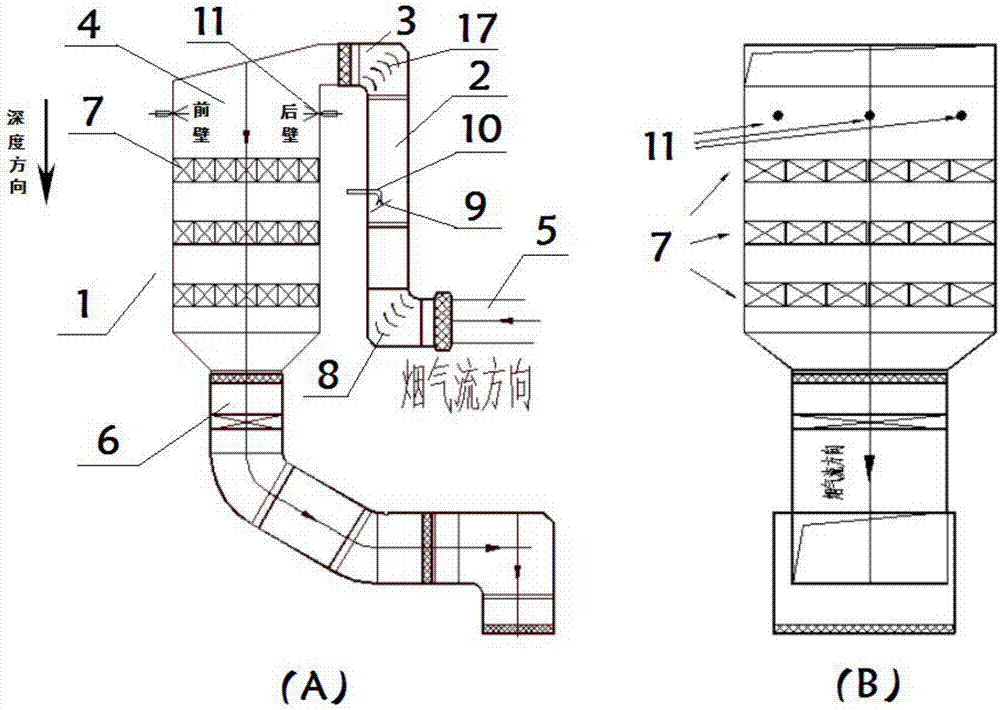
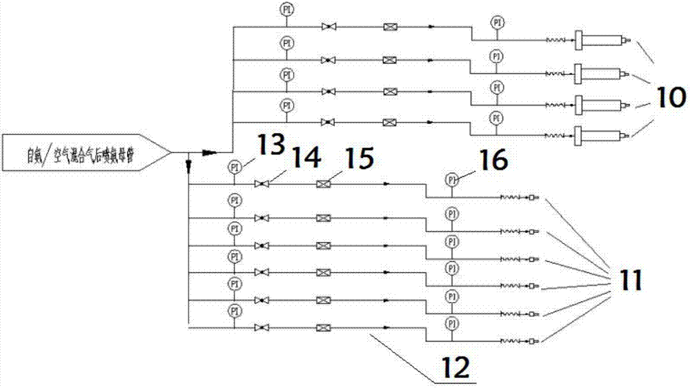
[0028] like figure 1 and 2 A graded ammonia injection SCR flue gas denitrification reactor is shown, including a reactor body 1, and the reactor body 1 sequentially includes a first vertical section 2, a horizontal connecting section 3 and a second vertical section 4 according to the flow direction of the flue gas A horizontal flue gas inlet pipe 5 is provided before the first vertical section 2, three layers of horizontally arranged catalysts 7 are arranged in the second vertical section 4, and a flue gas outlet pipe 6 is provided behind the second vertical section 4. One vertical section 2 is provided with a first-stage mixing and uniform distribution system, and the second vertical section 4 is provided with a second-stage mixing and uniform distribution system. A corner deflector 17 is provided at the corner connecting the first vertic...


PUM


Abstract

The invention discloses a device of achieving denitration and multistage ammonia spray of SCR (selective catalytic reduction) flue gas and a flue gas denitration method. The device comprises a reactor body, wherein the reactor body sequentially comprises a first vertical section, a level connection section and a second vertical section in a flue gas flow direction; a flue gas inlet pipeline is arranged before the first vertical section; the second vertical section is internally provided with a plurality of layers of catalysts arranged horizontally; a flue gas outlet pipeline is arranged after the second vertical section; the first vertical section is internally provided with a first stage mixing and uniform distribution system; the second vertical section is internally provided with a second stage mixing and uniform distribution system; the first stage mixing and uniform distribution system comprises a vortex mixer and a plurality of ammonia spray pipes with nozzles over against a standing vortex area of the vortex mixer; the second stage mixing and uniform distribution system is arranged above the catalysts and comprises a plurality of high-pressure spray guns flushly and oppositely arranged on a front wall and a back wall of the second vertical section; and the high-pressure spray guns adopt conical multihole nozzles. The device and the method can effectively solve the problem of a concentration deviation of ammonia in a posterior-anterior depth direction of the reactor.

Description

technical field [0001] The invention belongs to the technical field of power station environmental protection, and relates to a method and a device for controlling pollutants emitted by coal-fired boilers, and in particular to a device for realizing SCR flue gas denitrification by multi-stage ammonia injection and a flue gas denitrification method. Background technique [0002] The main components of NOx in the flue gas of coal-fired power plant boilers are NO and NO 2 , of which NO accounts for about 90%, NO 2 The generated amount accounts for about 5% to 10% of the total NOx emissions according to different combustion conditions, and the rest is mainly N 2 O. 70% of my country's total nitrogen oxide emissions come from the direct combustion of coal, and the power industry is a large coal-burning household in my country. Therefore, it is urgent to carry out NOx control and treatment in the atmospheric environment, and the NOx control of coal-fired power plants is the top ...

Claims


Application Information

Patent Timeline
IPC IPC(8): B01D53/86B01D53/56B01D53/76
CPCB01D53/8631B01D53/869B01D53/8696B01D2251/2062B01D2258/0283B01D2259/122
Inventor 时伟陈国庆黄启龙孙俊威
Owner GUODIAN SCI & TECH RES INST
Learn More