Manufacturing method of high-gloss film plate

A production method and stencil technology, applied in optics, printing plate preparation, opto-mechanical equipment, etc., can solve the problems of photoresist not being able to polymerize, hinder photoresist polymerization, and affect image fidelity, so as to reduce defective products and residues. product, reduce surface roughness, reduce the effect of variance

Active Publication Date: 2017-08-11
TIANJIN YUNCHENG PLATE MAKING
View PDF6 Cites 5 Cited by
  • Summary
  • Abstract
  • Description
  • Claims
  • Application Information

AI Technical Summary

Problems solved by technology

[0004] The disadvantage of this technical solution is that the surface of the exposed part of the plate is directly exposed to the air during the main exposure, and oxygen will hinder the polymerization of the photosensitive adhesive here, so that the photosensitive adhesive on the surface of the plate cannot undergo polymerization reaction, so that the laser engraving appears Therefore, the dot diameter of the screen will become smaller, and the 1:1 reproduction of the image from the black film to the printing plate cannot be realized
And the top of the highlight dot is rounded, which will affect the realism of the image

Method used


Image

  • Manufacturing method of high-gloss film plate
  • Manufacturing method of high-gloss film plate
  • Manufacturing method of high-gloss film plate

Examples


Embodiment 1

[0041] A method for making a high-gloss stencil, comprising the following steps,

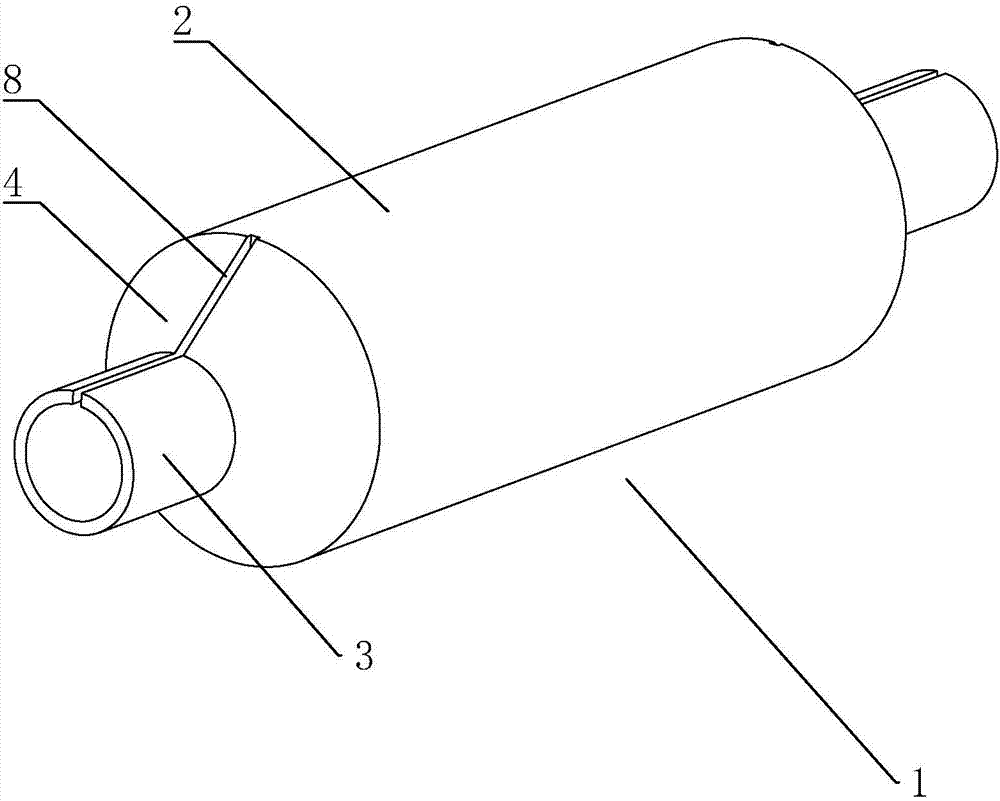
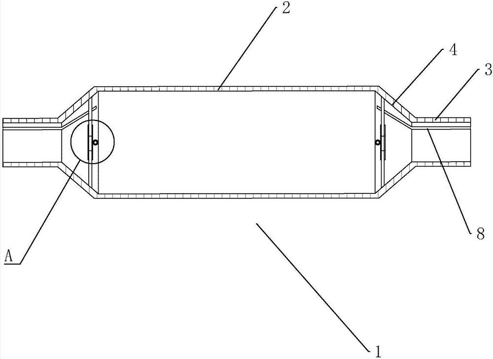
[0042] S1. Substrate production: use seamless steel pipe 2 to form plate roll 1, such as figure 1 , figure 2 and image 3 As shown, the two ends of the seamless steel pipe 2 are constricted to form the installation section 3, the seamless steel pipe 2 and the installation section 3 are arranged obliquely to form the transition section 4, and the outer wall of the installation section 3 is provided with a compensation groove 8 along its axial direction. 8 connected to the transition section 4;

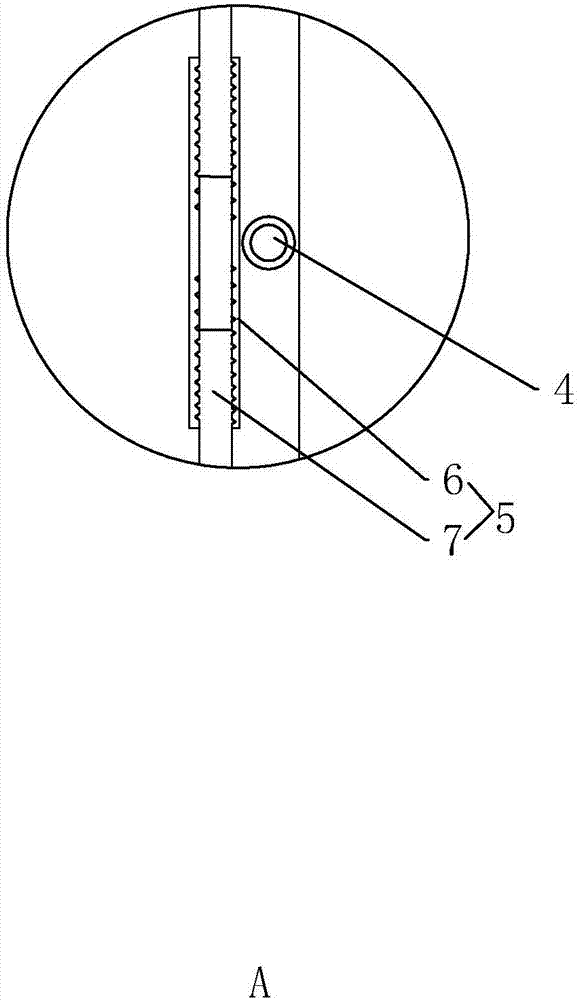
[0043] A reinforcing rod 5 is welded and fixed in the transition section 4, and the reinforcing rod 5 is arranged radially along the seamless steel pipe 2, and two reinforcing rods 5 are arranged in the two transition sections 4, and the two reinforcing rods 5 are arranged vertically;

[0044] The reinforcing rod 5 includes an adjusting rod 6 and a fixed rod 7, and the fixed rod 7 is provided with two...

Embodiment 2

[0054] Example 2: A method for making a high-gloss stencil, the difference from Example 1 is that the formula of the seamless steel pipe 2 is: C: 0.02wt%; Si: 0.72wt%; Mn: 0.04wt%; S P: 0.01wt%; Cr: 20.00wt%; Ni: 8.00wt%; Cu: 0.30wt%; N: 0.02wt%; Ti: 0.05wt%; the balance is Fe and unavoidable impurities .

Embodiment 3

[0055] Example 3: A method for making a high-gloss stencil, the difference from Example 1 is that the formula of the seamless steel pipe 2 is: C: 0.02wt%; Si: 0.72wt%; Mn: 0.04wt%; S P: 0.01wt%; Cr: 22.00wt%; Ni: 9.25wt%; Cu: 0.40wt%; N: 0.02wt%; Ti: 0.05wt%; the balance is Fe and unavoidable impurities .


PUM


Abstract

The invention discloses a manufacturing method of a high-gloss film plate. The method comprises the steps as follows: S1, manufacturing of a matrix: a plate roller is formed through machining of a seamless steel tube; S2, copper plating treatment of the matrix; S3, plate roller surface treatment after copper plating: the copper surface is ground; S4, gluing treatment: natural airing is performed after a photoresist is applied, black glue is applied, and drying is performed by the aid of an infrared drying machine; S5, laser image file manufacturing and laser engraving manufacturing of the plate roller; S6, developing of the plate roller: the black glue is removed, an exposed area of the photoresist is dissolved with an alkali, and a pattern of a non-exposed area is obtained; S7, electrotyping forming: the developed plate roller is placed in a nickel plating tank, electrotyping is performed, the photoresist after engraving and developing has the insulation performance, and meshes are formed in the development area after electrotyping; and S8, cleaning of the plate roller. Contact of the photoresist with oxygen before exposure is reduced, the condition that the photoresist cannot change drastically due to oxidation of the photoresist is avoided, the more stable flat top dot structure is obtained, and meanwhile, the smoothness difference of surfaces in different positions of the same plate roller is reduced.

Description

technical field [0001] The invention relates to a printing plate, in particular to a method for making a high-gloss stencil. Background technique [0002] The high-gloss stencil is mainly used for the printing of high-gloss patterns on the domestic leather surface. The process was a common engraving technology many years ago; after printing, it is relatively flat and dull, so the laser engraving process appeared on the market. [0003] For example, the patent whose notification number is CN103481638A discloses a plate roller for laser paper printing and its manufacturing process, which includes copper plating, encapsulation, laser engraving, corrosion, degumming and chrome plating. [0004] The disadvantage of this technical solution is that the surface of the exposed part of the plate is directly exposed to the air during the main exposure, and oxygen will hinder the polymerization of the photosensitive adhesive here, so that the photosensitive adhesive on the surface of th...

Claims


Application Information

Patent Timeline
Patent Type & Authority Applications(China)
IPC IPC(8): B41C1/18B41C1/05G03F7/00C25D1/10C25D3/38
CPCB41C1/05B41C1/18C25D1/10C25D3/38G03F7/00
Inventor 吕海荣
Owner TIANJIN YUNCHENG PLATE MAKING
Why Eureka
Try Eureka