Equipment for catalytic cracking and combustion of waste rubber and plastic of cement kiln head

A technology for catalytic cracking and waste rubber, which is applied in the direction of combustion type, cement production, combustion method, etc., to achieve the effect of simple equipment and low utilization cost

Pending Publication Date: 2017-08-11
长沙紫宸科技开发有限公司
View PDF9 Cites 1 Cited by
  • Summary
  • Abstract
  • Description
  • Claims
  • Application Information

AI Technical Summary

Problems solved by technology

Secondly, the known catalytic combustion technology, especially the high-temperature catalytic oxidation combustion technology, has great advantages over the conventional combustion technology and has the characteristics of significantly improving thermal efficiency. There is no research and practice of directly combining high-temperature catalytic cracking and catalytic oxidation combustion for cement kiln heads

Method used


Image

  • Equipment for catalytic cracking and combustion of waste rubber and plastic of cement kiln head
  • Equipment for catalytic cracking and combustion of waste rubber and plastic of cement kiln head

Examples


Embodiment 1

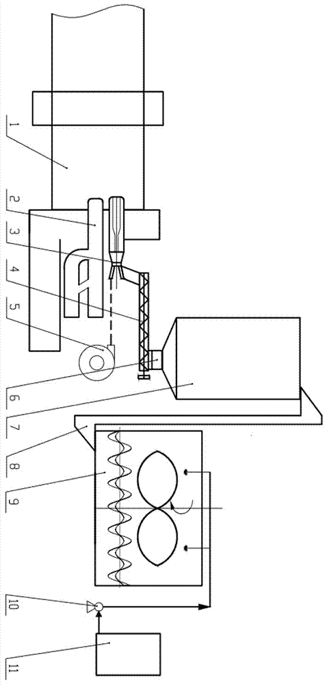
[0024] refer to figure 1 , a cement kiln kiln head catalytic cracking burning waste rubber or plastic equipment, including pulverized coal burner 2, waste fuel swirl burner 3, lock air feeder 4, high-pressure fan 5, feeder 6, Waste fuel bin 7, conveyor I 8, homogenizer 9, feed pump 10 and catalytic cracking oxidant storage tank 11, the feed pump 10 is connected to the liquid outlet of catalytic cracking oxidant storage tank 11 through different pipelines , the atomizing spray liquid inlet pipe of homogenizer 9 is connected, and the discharge end and the feed end of described conveyor I8 are respectively connected with the feed inlet of modified waste fuel bunker 7 and the discharge port of homogenizer 9. The bottom discharge port of the waste fuel bin 7 is connected with the feeder 6, the feeder 6 is connected with the wind lock feeder 4, and the wind lock feeder 4 is connected with the waste The feed port of the fuel swirl burner 3 is connected, and the high-pressure blower ...

Embodiment 2

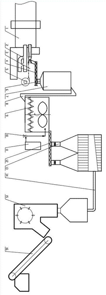
[0029] refer to figure 2 , a cement kiln kiln head catalytic cracking burning waste rubber or plastic equipment, including pulverized coal burner 2, waste fuel swirl burner 3, lock air feeder 4, high-pressure fan 5, feeder 6, Waste fuel bin 7, conveyor I 8, homogenizer 9, metering pump 10, catalytic cracking oxidant storage tank 11, batching and feeding device 12, plastic / rubber shredded waste storage bin 13, conveyor II 14, crushing The device 15 and the conveyor III16, the discharge end of the conveyor III16 is connected to the feed port of the crushing device 15, the discharge end and the feed end of the conveyor II14 are respectively connected to the plastic / rubber shredded waste storage bin The feeding port of 13 and the discharging port of crushing device 15 are connected, and the batching and feeding device 12 is respectively connected with the bottom discharge port of plastic / rubber crushed waste storage bin 13 and the feeding port of homogenizer 9, The meter feed pu...


PUM


Abstract

The invention provides equipment for catalytic cracking and combustion of waste rubber and plastic of a cement kiln head. The equipment comprises a pulverized coal burner, a waste fuel swirling burner, an airlock feeder, a high pressure fan, a meter feeder, a waste fuel bin, a conveyor I, a homogenizer, a meter feeding pump and a catalytic cracking oxidant storage tank. The equipment is simple, and relatively mature equipment is provided for selection; waste tires/waste plastic is used as alternative fuel, and the utilization cost is low; the equipment is high in economy and convenient for popularization; environmental pollution caused by the waste tires/waste plastic can be reduced effectively, and energy consumption and environmental pollution in the recycling and machining process of the waste tires/waste plastic are reduced, in favor of environmental protection; the invention provides new economic and practical equipment for utilizing the waste tires/waste plastic as the alternative fuel of the kiln head for cement enterprises, in favor of energy saving, emission reduction, cost decrease and benefit improvement of the cement enterprises.

Description

technical field [0001] The invention relates to the technical field of environmental protection equipment, in particular to equipment for catalytically cracking and catalytically burning waste rubber and plastics at the cement kiln head of a dry process cement production line. Background technique [0002] At present, the actual production capacity of my country's cement reaches 4.5 billion tons, about 3 tons per capita, accounting for more than 60% of the world's total cement production capacity, and cement production is recognized as an industry with high energy consumption and high pollution. The inevitable trend of emission reduction. But as we all know, the core of the cement kiln clinker production system is to burn two fires, that is, one fire at the kiln head and one fire at the calciner. The firing quality of clinker depends more on the one fire at the kiln head. , because the firing temperature of ordinary silicate clinker is 1450°C, that is, the temperature of the...

Claims


Application Information

Patent Timeline
Patent Type & Authority Applications(China)
IPC IPC(8): F27B7/34F23G7/12
CPCF23G7/12F27B7/34F23G2900/50202F23G2209/281F23G2209/28F23G2204/101F23G2201/80F23G2201/302Y02A50/20Y02P40/125
Inventor 尹小林
Owner 长沙紫宸科技开发有限公司
Why Eureka
Try Eureka