
X-ray diffraction in-situ characterization method of film orientation crystal growth

A thin film orientation and X-ray technology, which is applied in the field of thin film crystal phase structure characterization, can solve the problems of in-situ characterization, long characterization time, and insufficient detection depth.

Active Publication Date: 2017-08-22
HEFEI UNIV OF TECH
View PDF3 Cites 10 Cited by
  • Summary
  • Abstract
  • Description
  • Claims
  • Application Information

AI Technical Summary

Problems solved by technology

[0006] Problems existing in the existing technology: electron diffraction requires the sample to be thin enough, often requires complex sample preparation procedures, cannot be characterized in situ, and takes a long time to characterize; the use of synchrotron radiation X-ray in-plane diffraction technology has the advantage of surface sensitivity, but the detection depth Insufficient, and it is necessary to obtain the external total reflection angle of the film in advance (θ c ); high requirements on the accuracy of the optical system and the positioning accuracy of the sample; based on the above problems, the present invention provides an X-ray diffraction in-situ characterization method for film orientation crystal growth

Method used


Image

  • X-ray diffraction in-situ characterization method of film orientation crystal growth
  • X-ray diffraction in-situ characterization method of film orientation crystal growth
  • X-ray diffraction in-situ characterization method of film orientation crystal growth

Examples


Embodiment 1

[0069] Analysis of lattice constants of oriented thin films prepared by pulling TIPS pentacene with different solvents:

[0070] The initial input lattice parameters here come from references, and δ can be a number greater than 1 and less than 10.

[0071] Initial input (a b c α β γ δ) = [7.75 7.96 17.02 104.3 87.4 99.6 1.85].

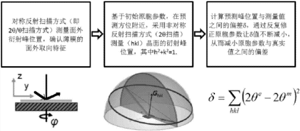
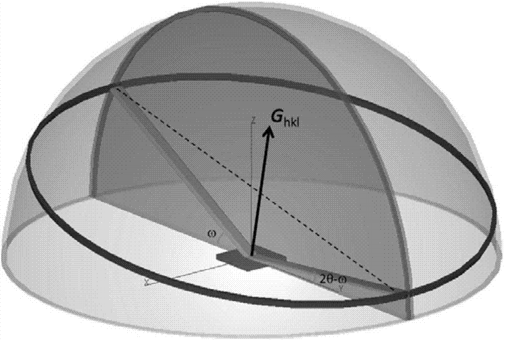
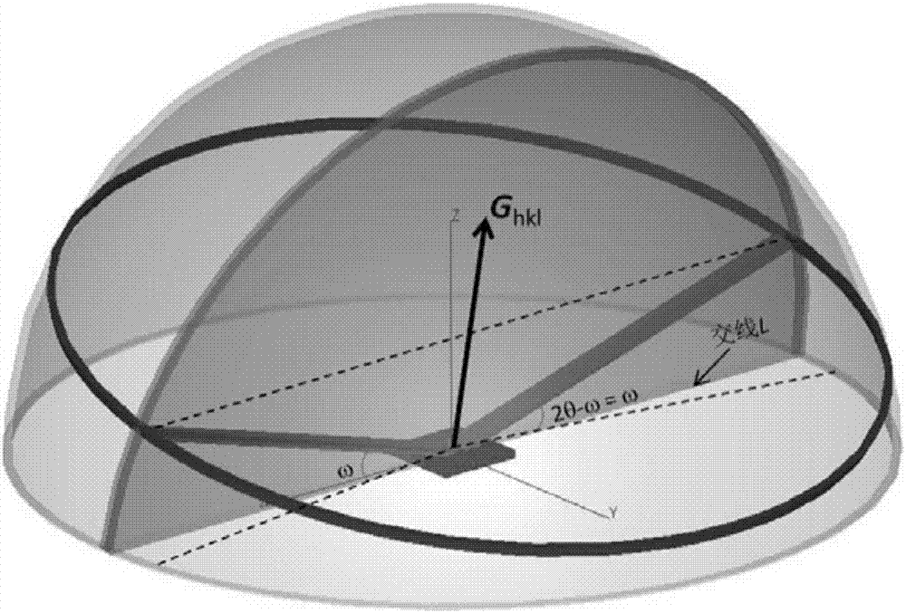
[0072] Under the coplanar constraint, calculate a series of (hkl) predicted test orientation data such as Image 6 , where h 2 +k 2 =1, l=7, 8, 9; the crystal plane index (Miller index) and its predicted deflection angle 2θ in line with the asymmetric reflection test conditions e Such as Figure 7 Shown; measured l = 8 crystal plane diffraction deflection angle 2θ m Such as Image 6 As shown, according to the out-of-plane diffraction peak positions and Image 6 In the asymmetric diffraction measurement, the continuously optimized lattice parameters and the deviation δ between the predicted peak position and the measured peak position are calcula...

Embodiment 2

[0074] Lattice constant analysis of C8-BTBT oriented film prepared by solution method:

[0075] The initial input lattice parameters here come from references, and δ can be a number greater than 1 and less than 10.

[0076] Initial input (a b c α β γ δ) = [5.91 7.88 29.12 90 91 90 1.85].

[0077] The lattice parameter analysis process and output results of C8-BTBT film are as follows Figure 9 As shown, the deviation δ is still greater than 1 after multiple cycles of calculation, and the deviation is relatively large. The in-plane texture of the film can be further finely analyzed based on the condition of asymmetric reflection scanning by making a pole figure, and the measurement orientation can be corrected based on the corresponding results. Measurement accuracy can be improved.


PUM


Abstract

The invention discloses an X-ray diffraction in-situ characterization method of film orientation crystal growth. The in-situ characterization method comprises the steps of firstly utilizing a symmetrical reflective scanning method to measure out-plane diffraction peak position of a film and determining an out-plane orientation characteristic of the film; then utilizing an asymmetrical reflective scanning method to obtain the diffraction peak position of a crystal face set near a predicted orientation based on initial primitive cell parameters, wherein crystal faces of the crystal face set form inclined included angles with a substrate; calculating out the difference delta between the diffraction peak position obtained by measurement and a prediction value based on the initial primitive cell parameters and continuously reducing the delta through lattic parameter correction and loop iteration calculation until the delta is small enough to obtain more accurate lattic parameter information. According to the X-ray diffraction in-situ characterization method disclosed by the invention, a computer-assisted calculating method is utilized, high enough analysis accuracy can be obtained within several seconds, and output data can be directly utilized as an input value of the next measuring period; thus, a high-speed dynamic measuring and analyzing system is formed.

Description

technical field [0001] The invention relates to an X-ray diffraction in-situ characterization method for film oriented crystal growth, and belongs to the technical field of film crystal phase structure characterization. Background technique [0002] Thin films prepared by solution methods, especially those grown by orientation, usually exhibit out-of-plane or in-plane orientation growth behavior. For example, ZnO thin films prepared from sol-gel precursors by using the pulling method thin film preparation technology can exhibit the out-of-plane preferred orientation of (001) or (100) direction. In organic materials, this kind of oriented growth is more common, and the control and adjustment of the lattice structure can be realized through molecular structure design, combined with solvent selection and substrate modification and other technological means. In particular, conjugated small organic molecules can simply control their growth rate or use different organic solvents ...

Claims


Application Information

Patent Timeline
IPC IPC(8): G01N23/20
CPCG01N23/20
Inventor 王向华顾勋
Owner HEFEI UNIV OF TECH
Learn More