Multi-layer reciprocating type gasified combustion furnace

A combustion furnace, reciprocating technology, applied in the direction of incinerator, combustion method, combustion type, etc., can solve the problems of long residence time, influence of burnout rate, large size of mechanical grate, etc., to reduce the volume of the incinerator and adapt to the scope The effect of widening and investment reduction

Pending Publication Date: 2017-09-05
BEIJING BUILDING MATERIALS ACADEMY OF SCI RES
View PDF4 Cites 14 Cited by
  • Summary
  • Abstract
  • Description
  • Claims
  • Application Information

AI Technical Summary

Problems solved by technology

Due to changes in the moisture content, shape, and calorific value of the waste, the size of the mechanical grate is usually large, and the cost of investment and maintenance is high.
Secondly, due to the high water and low heat characteristics of garbage, the uniformity and drying of the cloth have a great influence on the combustion effect. The dehydration and dry combustion of the existing mechanical incinerator is mainly completed by the mechanical grate, which has a long residence time and a large volume of the grate, which affects the burnout rate.

Method used


Image

  • Multi-layer reciprocating type gasified combustion furnace
  • Multi-layer reciprocating type gasified combustion furnace

Examples


Embodiment Construction

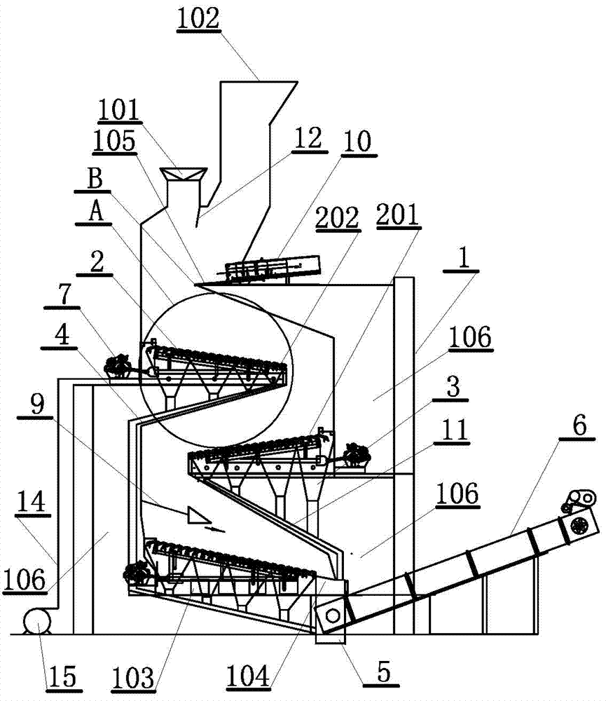
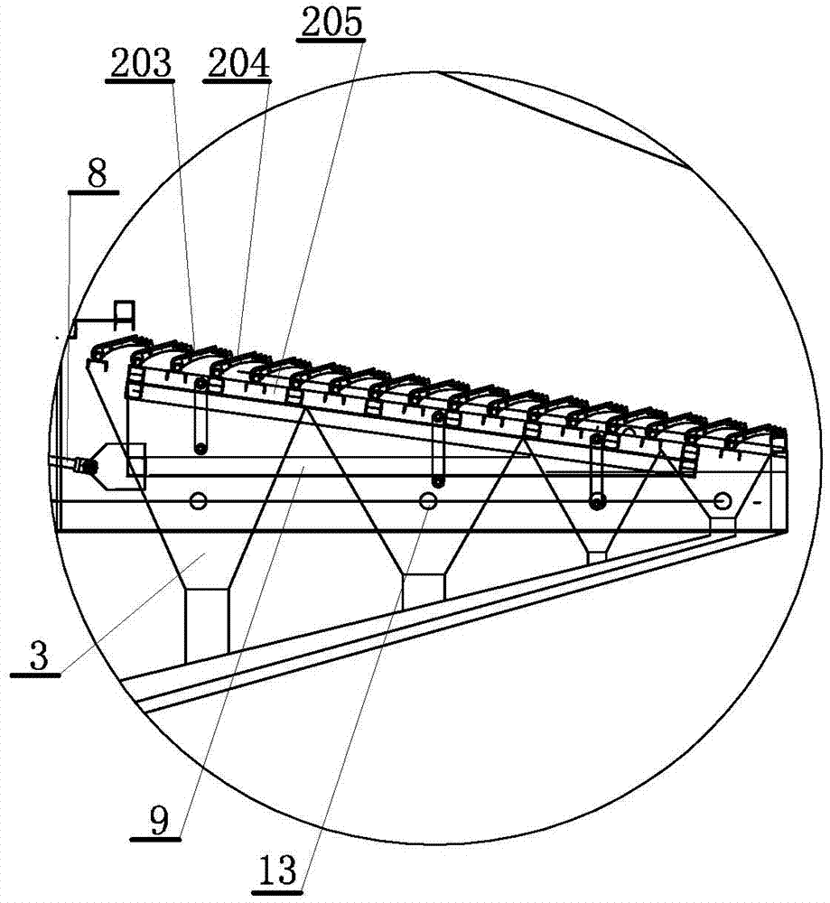
[0026] A multi-layer reciprocating gasification combustion furnace, such as figure 1 and figure 2 As shown, the multi-layer reciprocating gasification combustion furnace includes a combustion furnace body 1, which is a vertical cylindrical furnace body, and a gasification flue gas discharge port 101 and a gasification raw material garbage inlet 102 are arranged at the upper end of the combustion furnace body. , the gasification flue gas discharge port is used to connect the device or equipment that uses gasification flue gas, the feed port is set higher than the gasification flue gas discharge port, and the lower end side of the combustion furnace body is provided with a combustion gas inlet 103 and gasification raw material waste combustion The rear slag outlet 104; wherein, the hearth in the furnace body is provided with multi-layer fire grate 2 vertically from top to bottom, and at least three rows are shown in the figure, and each layer of fire grate is inclined downward,...


PUM


Abstract

The invention discloses a multi-layer reciprocating type gasified combustion furnace comprising a combustion furnace body. A gasified fume discharging outlet and a gasified raw material garbage feeding inlet are formed in the upper end of the combustion furnace body, and a combustion gas inlet and a slag tapping outlet after combustion of gasified raw material garbage are formed in the lower end side of the combustion furnace body; a hearth in the furnace body is vertically provided with multiple layers of furnace rows from top to bottom; each layer of furnace row is arranged in a downward-inclining mode; the high end sides of the furnace rows at the lower layers stretch out of the low end sides of the furnace rows at the upper layers to enable the gasified raw material garbage on the furnace rows at the upper layers to fall into the high end sides of the furnace rows at the lower layers from the low end sides of the upper layers along the inclining gradient; and dust receiving funnels are arranged on the bottom face of the furnace row at each layer and connected with a dust discharging pipeline to output dust from the bottom side of the combustion furnace body. Because the garbage is fully dried and dehydrated through the multiple layers of furnace rows in the hearth, the heat value is increased, the combustion effect is more full, the structure is simple, the size of the combustion furnace is decreased greatly, investment is reduced, thermal decomposition gasified combustion of the furnace row at each layer can be achieved, and the application range of raw materials is wide.

Description

technical field [0001] The invention relates to the fields of environmental protection equipment and fuel substitution. In particular, it relates to a multi-layer reciprocating gasification combustion [0002] Furnace is a gasification combustion device for domestic garbage, sludge, RDF and other wastes. Background technique [0003] Domestic waste incineration is an important means of recycling, reducing and harmless waste. Waste incinerators mainly include mechanical grate, rotary furnace, fluidized bed incinerator and other types. In addition to the requirements for the characteristics of waste fuel, these technologies also require the selection of key equipment such as grates and grates. Due to changes in the moisture content, shape, and calorific value of the waste, the size of the mechanical grate is usually large, and the cost of investment and maintenance is high. Secondly, due to the high water and low heat characteristics of garbage, the uniformity and drying o...

Claims


Application Information

Patent Timeline
Patent Type & Authority Applications(China)
IPC IPC(8): F23G5/027F23G5/04F23G5/44F23H7/00
CPCF23G5/0276F23G5/04F23G5/44F23G5/444F23H7/00
Inventor 刘海兵顾军刘卫民
Owner BEIJING BUILDING MATERIALS ACADEMY OF SCI RES
Why Eureka
Try Eureka