
Low-energy consumption kitchen wastewater treatment process and equipment

A technology for kitchen waste water and treatment equipment, which is applied in water/sewage treatment, multi-stage water/sewage treatment, water/sludge/sewage treatment, etc. It can solve the problem of increasing the complexity of system operation, complex operation, and water intake requirements High-level problems, to achieve the effect of being conducive to the reproduction of bacteria, low overall investment, and reducing sludge loss

Inactive Publication Date: 2017-09-08
WUXI MASHENG ENVIRONMENT ENERGY TECH CO LTD
View PDF5 Cites 2 Cited by
  • Summary
  • Abstract
  • Description
  • Claims
  • Application Information

AI Technical Summary

Problems solved by technology

In the actual implementation of the kitchen wastewater treatment process, the whole set of equipment still has the problems of high energy consumption and complicated operation. First, due to the high ammonia nitrogen characteristics of the wastewater, a large amount of oxygen needs to be supplemented; second, the external tubular ultrafiltration membrane system uses membrane The pressure difference between the inside and outside of the pipe permeates the water, and a high-pressure circulating pump is required; again, the tubular ultrafiltration membrane has high requirements for the incoming water, and no impurities can enter the membrane system. A pretreatment device needs to be installed to increase the complexity of the system operation.

Method used


Image

  • Low-energy consumption kitchen wastewater treatment process and equipment

Examples


Embodiment Construction

[0049] to combine figure 1 , which describes the first specific embodiment of the present invention in detail, but does not limit the claims of the present invention in any way.

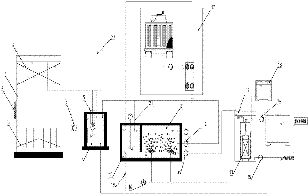
[0050] like figure 1 As shown, the low-energy-consumption treatment equipment for kitchen wastewater in this embodiment includes a high-efficiency denitrification reactor 1, and a three-phase phase that realizes the three-phase separation of water, gas, and solid and prevents sludge loss is arranged on the top of the high-efficiency denitrification reactor 1. Separator 2, set water distributor 4 at the bottom of high-efficiency denitrification reactor 1, water distribution pool 7, aerobic pool 8, anoxic pool 10, cooling heat exchange system 17 connected to aerobic pool 8 and anoxic pool 10 respectively , cleaning pool 18,

[0051] It also includes a water distributor 5, which is arranged on the top of the water distribution tank 7, receives the water output from the high-efficiency denitrification ...


PUM


Abstract

The invention relates to a low-energy consumption kitchen wastewater treatment process and low-energy consumption kitchen wastewater treatment equipment. The low-energy consumption kitchen wastewater treatment equipment comprises a water distribution tank, a high-efficiency denitrification reactor, an anoxic tank, an aerobic tank, a built-in MBR system and a cooling heat transfer system, wherein the high-efficiency denitrification reactor is connected with the water distribution tank through a pipeline and a circulating pump; the water distribution tank is connected with the anoxic tank, the aerobic tank and the built-in MBR system; the anoxic tank is connected with the aerobic tank; the aerobic tank is provided with an aeration device; the aerobic tank is connected with the built-in MBR system; the built-in MBR system is connected with a cleaning tank; through arrangement of the water distribution tank, and after effluent water of the denitrification reactor is mixed with aerobic backwater, water enters from the bottom of the reactor circularly, so that growth of anaerobic ammoxidation bateria and denitrifying bacteria is promoted and the denitrification efficiency is improved; and through adoption of the built-in MBR system, the running energy consumption is low, only a low-suction range suction pump is required during membrane assembly running, and the running expense is lower than 1 / 10 of that of the conventional membrane product.

Description

technical field [0001] The invention relates to the technical field of kitchen waste wastewater treatment, in particular to a low-energy-consumption treatment process and equipment for kitchen waste water. Background technique [0002] Kitchen wastewater comes from the effluent of kitchen waste after pretreatment and anaerobic fermentation treatment. With the development of my country's social economy and the rapid development of the catering industry, the amount of kitchen wastewater is increasing day by day. If it is directly discharged without effective treatment, it will cause serious pollution to natural water bodies and the social environment. However, the quality of kitchen wastewater is complex, with the characteristics of high COD (Chemical OxygenDemand), high ammonia nitrogen, high SS (suspend solid) and high salinity, making it difficult to treat. [0003] The waste water treatment process of the existing kitchen waste treatment plants generally has problems such...

Claims


Application Information

Patent Timeline
IPC IPC(8): C02F9/14
CPCC02F1/001C02F1/586C02F3/30C02F9/00
Inventor 高瑞丽岳婵媛戴如娟闫林涛
Owner WUXI MASHENG ENVIRONMENT ENERGY TECH CO LTD
Learn More