Oil gas production process of high-temperature oil gas dedusting device after dry distillation of oil shale

A technology of dust removal device and production process, which is applied in the direction of gas dust removal, combined device, petroleum industry, etc., which can solve the problems of poor dust removal effect, achieve the effects of reducing consumption, high-precision filtration, and reducing processing equipment

Inactive Publication Date: 2017-09-15
LUOYANG CEMENT ENG DESIGN & RES INST
View PDF9 Cites 3 Cited by
  • Summary
  • Abstract
  • Description
  • Claims
  • Application Information

AI Technical Summary

Problems solved by technology

The characteristics of the particles also change under high temperature conditi

Method used


Image

  • Oil gas production process of high-temperature oil gas dedusting device after dry distillation of oil shale
  • Oil gas production process of high-temperature oil gas dedusting device after dry distillation of oil shale

Examples


Embodiment 1

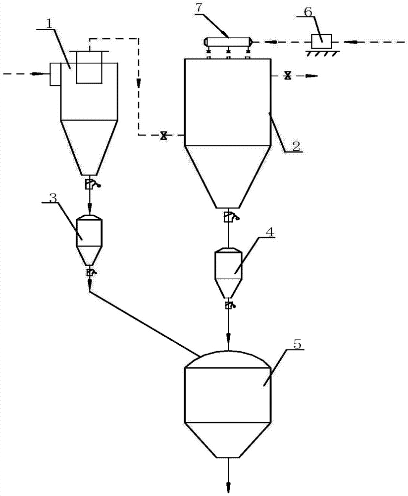
[0024] A metal membrane filter 2 is installed on one side of the gravity dust collector 1, an oil and gas transmission pipeline is installed between the upper outlet of the gravity dust collector 1 and the lower inlet of the metal membrane filter 2, and dusty oil and gas are installed outside the upper mouth of the gravity dust collector 1 At the inlet, dusty oil and gas holes are reserved between the gravity dust collector 1 and the dusty oil and gas inlet; the bottom of the gravity dust collector 1 is set as a conical bottom, and the coarse dust intermediate cooling chamber 3 is set under the gravity dust collector 1, and the gravity dust collector A dust conveying pipeline for high-temperature coarse-grain dust is set between the bottom of 1 and the intermediate cooling chamber 3 for coarse-grain dust;

[0025] The bottom of the metal membrane filter 2 is set as a conical bottom, the fine particle dust intermediate cooling chamber 4 is arranged under the metal membrane filte...

Embodiment 2

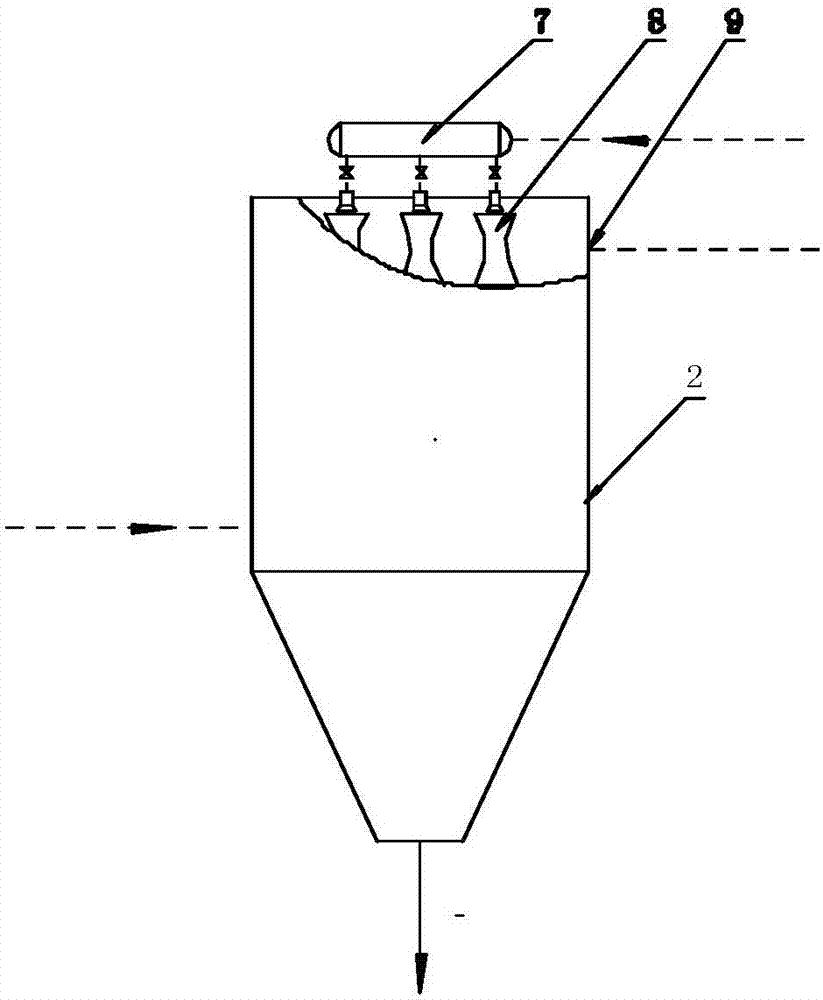
[0030] The dusty oil and gas containing fine particle powder separated from the dusty oil and gas is discharged through the upper outlet of the gravity dust collector 1, and enters the lower part of the metal membrane filter 2 through the oil and gas conveying pipeline, and the dusty oil and gas in the metal membrane filter 2 passes through when it rises. Metal membrane filter element, the metal membrane filter element collects and separates fine particle dust in dusty oil and gas.

Embodiment 3

[0032] After the fine particle dust in the dusty oil and gas is collected and separated, the oil and gas that rises to the upper part of the metal membrane filter 2 is clean oil and gas, and the clean oil and gas pass through the clean oil and gas outlet 9 on the upper side of the metal membrane filter 2 and enter the lower A production workshop.


PUM


Abstract

The invention discloses an oil gas production process of a high-temperature oil gas dedusting device after dry distillation of oil shale. For dust-containing oil gas of an oil shale dry distillation furnace, a gravity deduster, a metal film filter, an inert gas heater and an inert gas compression device are started; after dry distillation of the oil shale, and high-temperature dust-containing oil gas enters a dust-containing oil gas inlet of the gravity deduster through a pipeline to enter the gravity deduster; the gravity deduster separates thick dust particles in the dust-containing oil gas through rotary cutting and centrifugal gas; the thick particles separated out from the dust-containing oil gas slide into the bottom of the gravity deduster and enters a thick particle dust intermediate cooling bin through a pipeline at an outlet for cooling, and thick particle dust after being cooled enters an ash tank through a pipeline; through reverse blowing of inert gas, thin particle dust falls into a cooling bin below the bottom of the metal film filter. The oil gas production process includes: step 1, gravity dedusting; step 2, high-precision filtering through the metal film filter. By the oil gas production process, energy consumption is lowered, and dedusting effect is improved.

Description

technical field [0001] The invention relates to high-temperature oil and gas dedusting after oil shale dry distillation, in particular to an oil and gas production process of a high-temperature oil and gas dust removal device after oil shale dry distillation. Background technique [0002] At present, oil shale, also known as kerogen shale, is a solid combustible organic sedimentary rock with high mineral content. Oil shale can be pyrolyzed (low temperature dry distillation) to obtain shale oil similar to crude oil and gas similar to natural gas. my country's energy structure is coal-rich, oil-poor, and gas-poor. Shale oil and combustible gas, as supplements to conventional energy sources, have very important strategic significance for changing my country's energy structure and energy security. [0003] Oil shale undergoes low-temperature carbonization to obtain high-temperature oil and gas at 450°C. The dust removal of high-temperature oil and gas is a key problem in the o...

Claims


Application Information

Patent Timeline
IPC IPC(8): B01D50/00C10K1/02C10B53/06
CPCC10B53/06C10K1/02C10K1/024B01D50/20
Inventor 崔艳华赵迎朝代家聚缪祥来
Owner LUOYANG CEMENT ENG DESIGN & RES INST
Why Eureka
Try Eureka