High-wear-resisting flow guide type water nozzle body and manufacturing method thereof
A technology with high wear resistance and faucets, applied in valve details, valve housing structure, mechanical equipment, etc., can solve problems such as blockage, non-wear resistance, deformation, etc., and achieve the effect of streamline change obviously and streamline change rule
- Summary
- Abstract
- Description
- Claims
- Application Information
AI Technical Summary
Problems solved by technology
Method used
Image
Examples
Embodiment 1
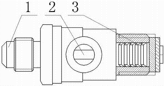
[0029] A high-wear-resistant flow-guiding faucet main body, which consists of a faucet main body 1 with a conical forging streamline concentrating toward the inner hole obtained through square-to-circle hot extrusion and swaging, and a faucet main body 1 that is arranged in the inner hole and shrinks with the faucet inner hole A diversion ring 3 with an acute-angle contour line at the mouth end, and a faucet valve 2 are also provided in the middle of the faucet main body 1 .
[0030] A method for manufacturing a high wear-resistant diversion nozzle body, comprising the following steps:
[0031] 1) Pre-preparation
[0032] ①Choose aluminum bronze copper billet as raw material;
[0033] ② Select forging equipment equipped with hydraulic generating device, rotary push device and air cooling device; select vacuum resistance furnace as initial forging heating equipment;
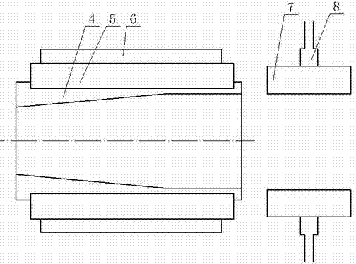
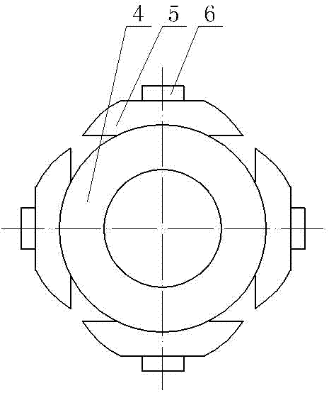
[0034] ③ Use four forged hammerheads 7 and matching hydraulic output device 8 as final forging and clamping t...
Embodiment 2
[0048] The whole is the same as Example 1, the difference is:
[0049] 2) forging
[0050]②The forging hammer head 7 linked with the rotary push device is pushed by the hydraulic generating device, and the copper billet is extruded into a forging billet with a nearly square cross section at a feed rate of about 5% for each deformation and a final deformation ratio of 45%;
[0051] ③Propel the forged billet with a nearly square cross-section at a speed of 0.25mm / s into the inner hole of the main body 4 of the ceramic tooling along the rotation axis on the basis of the joint rotation of the rotary push device and the forging hammer head 7;
[0052] ④ Install an air-cooling device at the outlet of the inner hole of the main body 4 of the ceramic tooling, and blow out nitrogen at a pressure of 3 bar for cooling;
[0053] ⑥Cool the forged copper billets within 10 minutes after forging at -75°C for 1.5 hours of ice-cooling treatment; then use 300°C for a time of (22d) min / mm based ...
Embodiment 3
[0058] 2) forging
[0059] ②The forging hammer head 7 linked with the rotary push device is pushed by the hydraulic pressure generating device, and the copper billet is extruded into a forging billet with a nearly square cross section at a feed rate of about 5% for each deformation and a final deformation ratio of 60%;
[0060] ③Propel the forged billet with a nearly square cross-section at a speed of 0.3mm / s into the inner hole of the main body 4 of the ceramic tooling along the rotation axis on the basis of the joint rotation of the rotary push device and the forging hammer 7;
[0061] ④ Install an air-cooling device at the outlet of the inner hole of the main body 4 of the ceramic tooling, and blow out nitrogen at a pressure of 5 bar for cooling;
[0062] ⑥Cool the forged copper billets within 10 minutes after forging at -85°C for 2 hours, and then temper them at 320°C for a time of (24d) min / mm based on the diameter of the copper billet. Forgings are required;
[0063] 3...
PUM
 Abstract
Description
Claims
Application Information
 - R&D
- Intellectual Property
- Life Sciences
- Materials
- Tech Scout
- Unparalleled Data Quality
- Higher Quality Content
- 60% Fewer Hallucinations
Browse by: Latest US Patents, China's latest patents, Technical Efficacy Thesaurus, Application Domain, Technology Topic, Popular Technical Reports.
© 2025 PatSnap. All rights reserved.Legal|Privacy policy|Modern Slavery Act Transparency Statement|Sitemap|About US| Contact US: help@patsnap.com


